In January of 2024 I decided to build an audio angle of attack instrument. This page attempts to summarize the most important aspects. This will mainly consist of technical details, for those interested. The full story is here: https://akaflieg.nl/index.php/tag/hobbes/
Inspiration
The inspiration consisted of a couple of things. First was the existing audio of attack meter present in the F4 Phantom:
Another inspiration was a previous job, where we made products with haptic feedback. I drove a car where the navigation system consisted of vibration motors in the driver’s seat. This was very relaxing. I later learnt that haptic feedback is processed in an old part of the brain. This reduces the mental energy required to process it, but also reduces response times. I saw this in patients who learn to walk with an artificial balance organ within 30 minutes of wearing it. Lesson learnt: how you convey information is very important.
Development
For development, I wanted to experiment with eXtreme Manufacturing. Since I had never designed PCBAs or even done anything serious with breadboards, I chose an iterative way of working to learn quickly. I ordered a new PCBA every two weeks from JLCPCB. Those took a week to arrive, making feedback rather quick. I asked coworkers for help when Google wasn’t enough. For PCBA design I used EasyEDA, which already contains footprints of parts that JLCPCB can place.
For CAD, I first used EasyEDA too. Later I switched to OpenSCAD, mainly because of it’s ability to be scripted easily. I eventually implemented Test Driven Development for CAD by checking for collisions between parts.
For the software, I used an existing codebase I had in C++20. Some things that were central to my codebase were:
- A templated class encapsulating any SI-unit possible, which automatically handles things like addition and multiplication too. This allowed for the compiler’s type checker to look if things look sane in my physics calculations.
- Following the Erlang “let it crash” philosophy, I split my program into communicating processes. Each process can crash (for foreseen or unforeseen reasons) and will be restarted quickly. This makes surviving transient bugs easier, and speeds up development in the face of those. It also makes the code more focused in the “happy path” instead of being littered with error handling.
- I heavily used Test Driven Development and CI/CD to increase confidence in the code.
- I didn’t optimize anything until needed. Implementations were kept as simple as possible.
Estimating AoA
Very early on in the project, I realised that measuring AoA is hard. Especially if you have never seen the gliders you’re going to measure it on.
Therefore I chose to estimate AoA by estimating C_L. And since I’m only interested in the glider’s approach to C_Lmax, I can even leave out more terms. I was left with: N / IAS^2.
Since I can’t predict C_Lmax, the pilot has to calibrate the system by pressing a PushButton while stalling the glider.
Feedback
For feedback I used a Passive Piezo Buzzer. This generated 80dB of sound at it’s resonant frequency of 2700Hz. I used tiny beeps, inspired by a Geiger Counter, to indicate the approach to stall. I deliberately chose not just to beep at the stall, but to give near-continuous feedback to generate a sense of situational awareness.
An exponential curve to translate the (normalized) C_L value into a beeping frequency was derived, such that:
- It beeps at 20Hz at the actual stall.
- It beeps at roughly 1Hz at circuit and landing speeds.
- It still beeps, but much slower at higher speeds.
Hardware
Following the eXtreme Manufacturing principle “Optimize for change”, I chose the Raspberry Pi Zero 2W as the computing platform for the project. I tuned the Pi down to 0.7 Watt power consumption and optimized for SD-card longevity. I used the Pi’s WiFi to upgrade software easily, by installing a Debian package that was generated by the CI/CD pipeline.
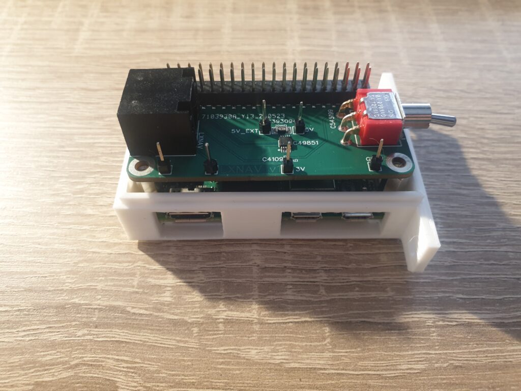
Since multiple input sources were available, I split my PCBA into two pieces: one for input and one for output. There existed an LXNAV input PCBA, which received 5V and 3.3V TTL UART. The IGC version received 12V and RS232 signal levels. These two PCBAs could be exchanged within 5 minutes.
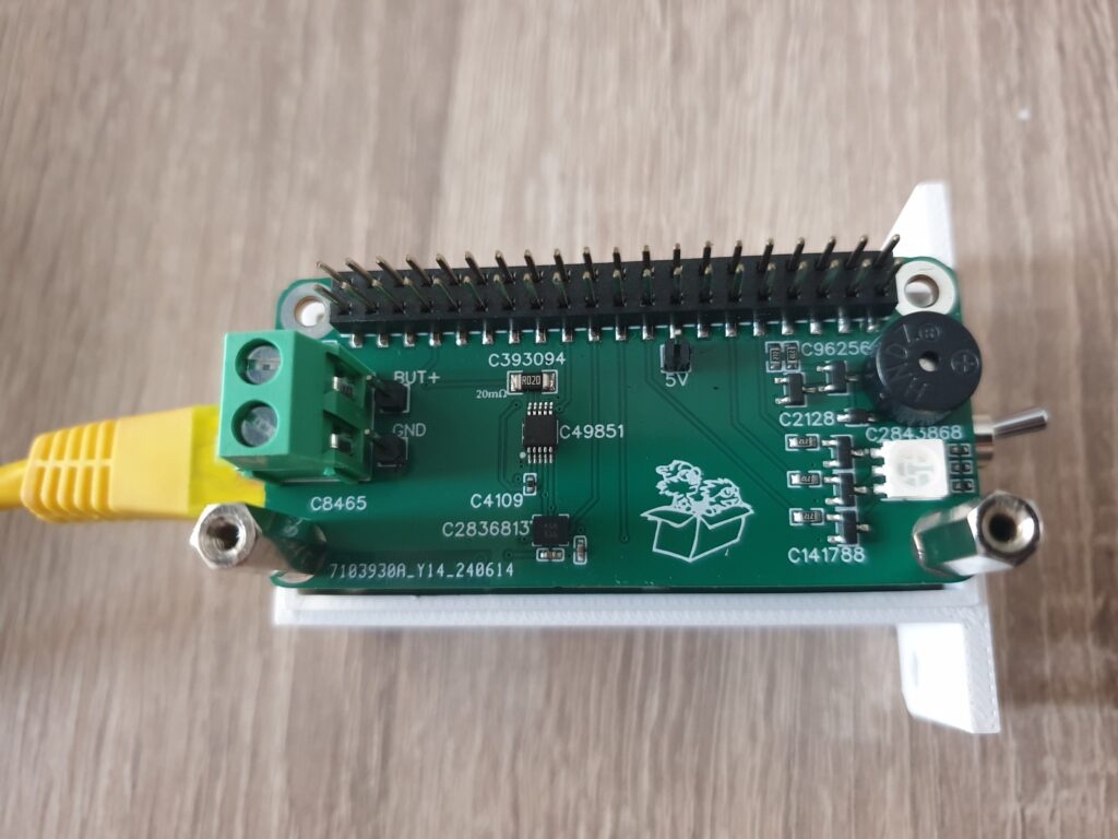
The output PCBA contained the Buzzer, the (connection for the) PushButton and an RGB-Led to indicate system status.
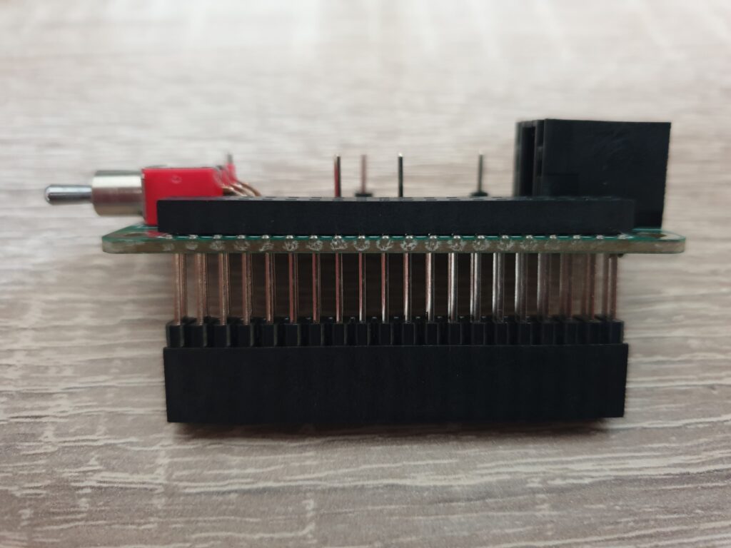
PCBAs were stacked using long header pins and a set of push-through female headers on top of the PCBAs.
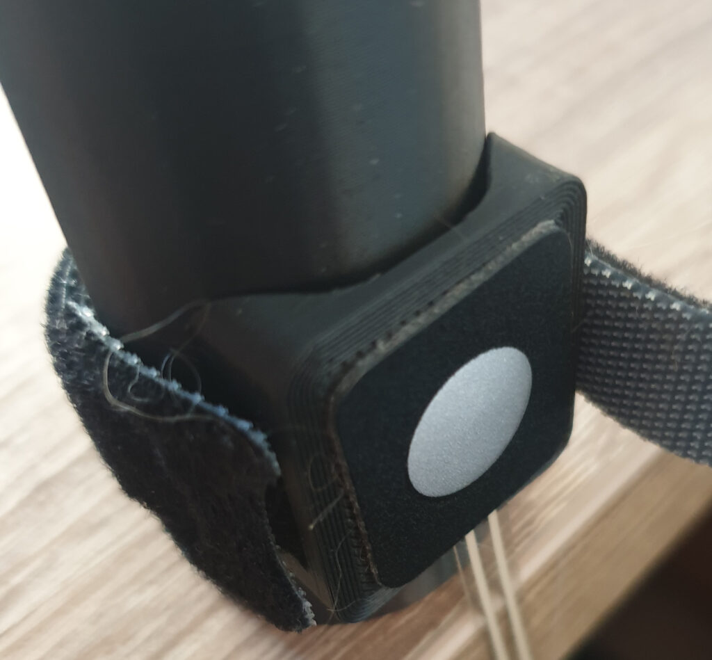
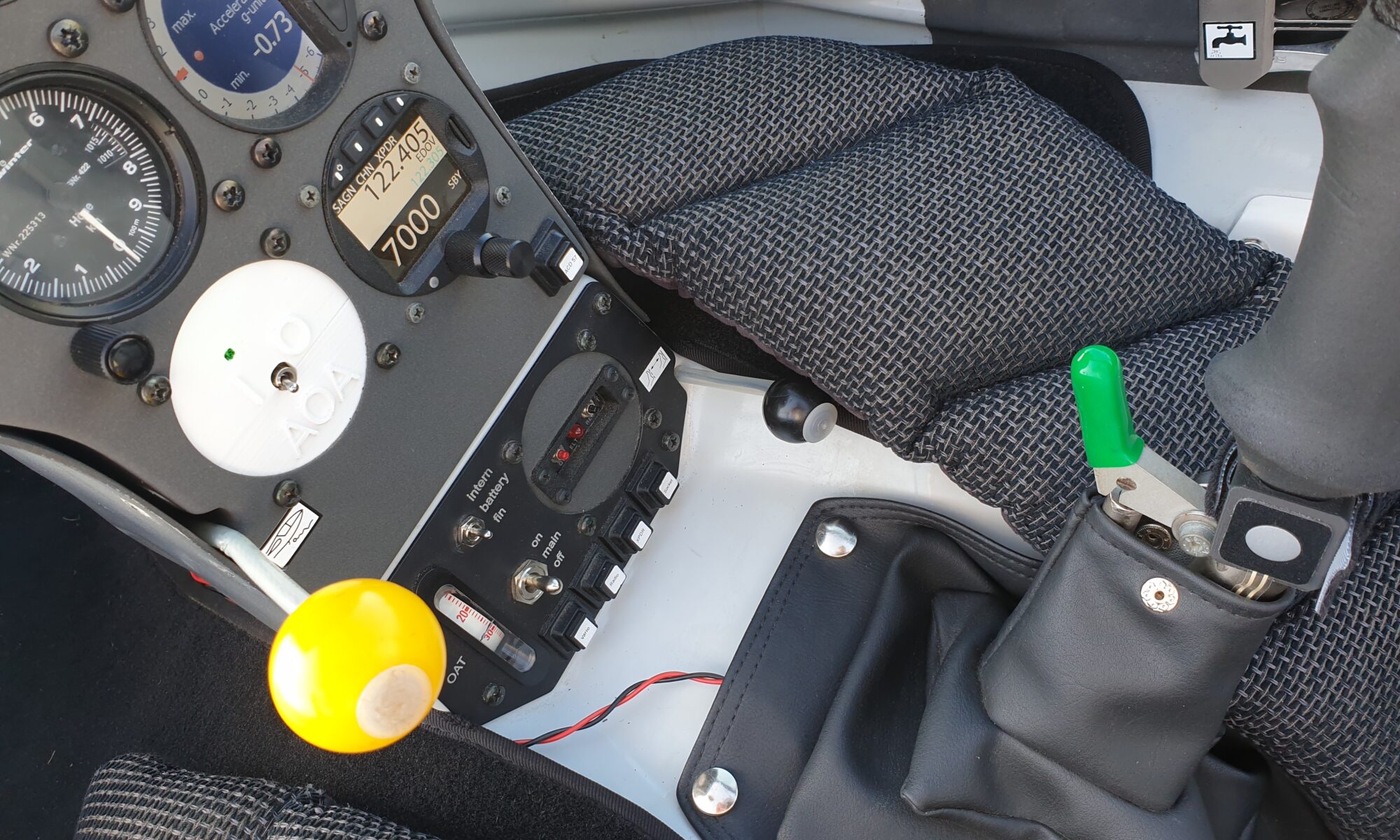
The PushButton was executed as a membrane button on a small 3D-printed adapter bracket. It was secured with a velcrow strap to the flight stick.
Results
It worked pretty well! Here is a demo of a base-to-final turn
And here is a 10 degrees skidded stall: