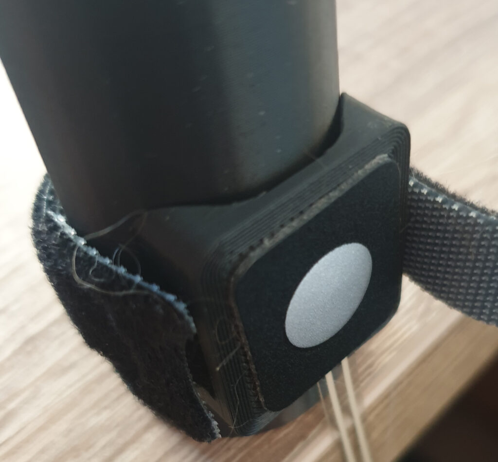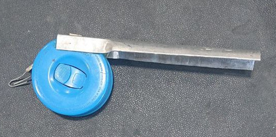
In 2024 I tested Hobbes, an acoustic angle of attack indicator. The feedback from that was quite clear: this shows promise, but the integration needs work. Not only was my instrument’s acoustic feedback similar to that of FLARM, causing some pilots to question which instrument they heard. Some pilots even complained that they even got a headache of hearing both my instrument and the variometer at the same time, and having to divide their attention between both devices.
This got me thinking about the state of avionics in gliders. Since I started gliding in 2003, I’ve seen avionics make their way into glider cockpits. However, we’re doing it wrong… let me tell you why.
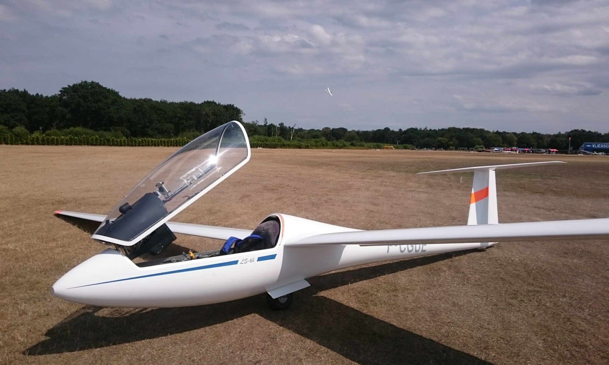
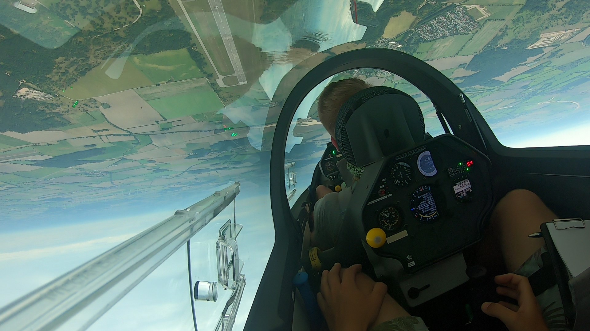
What a glider cockpit looks like
A modern glider cockpit is a collection of various instruments, which each do their own thing, combined in an instrument panel. Most manufacturers make a particular type of instrument. The interface to the pilot is – with the exception of moving map displays – a round gauge facing the pilot.
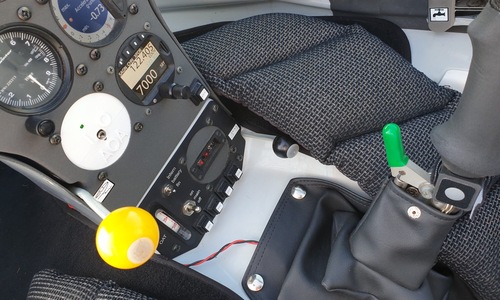
There are a lot of small instruments in a modern glider. Here is a list of what you are likely to see:
- A speedometer, altimeter, variometer
- A moving map display
- A VHF radio, transponder
- A traffic awareness device (FLARM)
Optionally, we might also see:
- Flap indicators, gear warning and canopy warning instruments
- Live wind indicators, tracking instruments
- Electronic water dump instruments, water dump instruments
- Battery conditioning instruments, solar charge controllers
- Canopy flashers
Electronics, Pneumatics and GNSS
Since each electronic system is separate, most manufacturers tell you to use a separate fuse for each instrument. Since we don’t want the fuses in the primary field of view of the pilot – ideally we spend no time interacting with them during flight – each instrument has a separate wire going to the fuse and a central ground point. As the number of instruments increases, the wiring becomes more and more complex… until you end up with something like this:
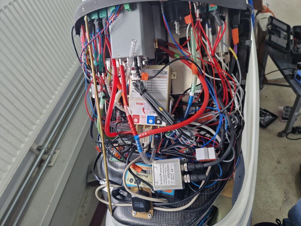
Most glider pilots know that – over time – the wiring behind the panel becomes a big mess. There’s usually little point in trying to understand what’s happening, so when you buy a second-hand glider some people just remove it all and start from scratch.
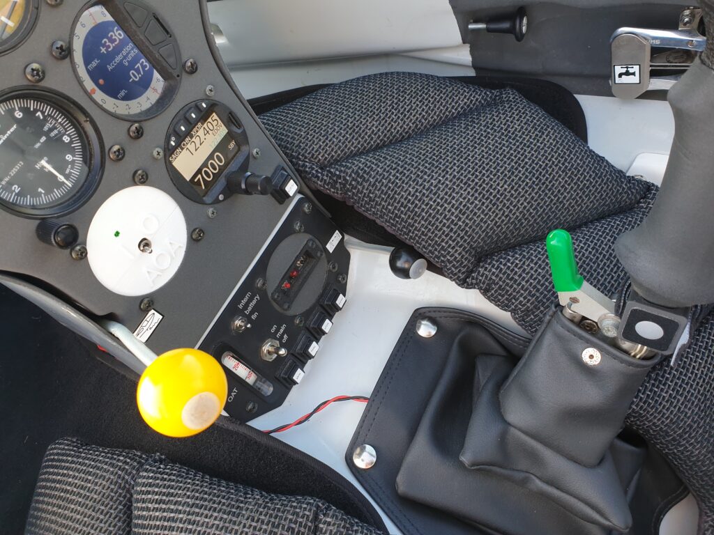
With the pneumatics the same happens as with the electronics, but less dramatic. With more instruments attached to a single pressure source the risk of interactions grows, as does the risk of leaking connections.
Most instruments want their own specific GNSS antenna and GNSS receiver. Thus, the panel (cover) becomes more and more crowded with GNSS antennae over time. When you remove the panel cover, it’s easy to pull on the cables, compromising the quality of the connection to the connectors.
Attention management
When multiple instruments are designed by different parties, they do not take into account each others’ presence in the cockpit. The result might be that the pilot is faced with multiple conflicting warnings, or might fly with multiple instruments that are (too) similar in their way of warning the pilot. This puts the burden on the pilot in the worst situation possible: when there is a complex emergency.
Integration
Most of the electronic instruments use a proprietary protocol (usually over RS232: more wires) if they talk to other devices. That means that integration between various types of equipment is difficult and labor-intensive. Not only do instruments not talk to each other. As a result of this they also have their own – incomplete – picture of the current situation. For example, when a glider flies backwards over the ground in a strong wave GPS-based instruments work in reverse. Again the burden is laid on the pilot, who is forced to keep a mental model of each instrument in their head.
What we need
In order to break free from what we consider to be “normal”, what we’re simply used to from prolonged exposure, we might ask ourselves: “What would be ridiculous not to have in glider cockpits in 25 years?”. This is my take…
It would be absolutely ridiculous not to have cockpits that direct our attention primarily outward. It would be ridiculous if we would not have systems that primarily manage themselves. It would be ridiculous if we would fly around with systems that we have to adapt to instead of systems that communicate towards us in the way that’s most intuitive to us. And it would be ridiculous if our systems didn’t allow us to cooperate seamlessly when flying cross-country.
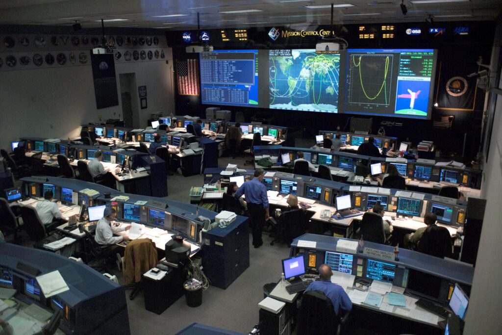
A glider cockpit should be a miniaturized version of a control room. We should be able to answer questions like:
- Where are we?
- What is our current situation?
- What just happened?
- What’s about to happen?
- What can we do?
And we should have to perform as little mental effort as possible to do so. It would be absolutely ridiculous if the burden of the increasing complexity in our cockpits was put on the pilot. Our systems should demand as little attention as possible, and we as pilots should look inside the cockpit only briefly in order to update our situational awareness with information we cannot see out the window and that cannot be conveyed in other ways (acoustically, tactile, …).
Our cockpit systems should manage themselves and recover from non-critical errors or be adaptive enough to gracefully degrade in their performance.
This means that an instrument is the wrong abstraction altogether. Each instrument maintains its own partial model of the world and asserts it independently — the pilot is the only place those models ever meet. We’ve digitized that arrangement without questioning it; electronic instruments are still just pneumatic instruments with screens.
The right abstraction is the flight situation — one coherent model of what is happening, maintained by the system rather than assembled by the pilot. Sensors become inputs to that model, not endpoints in their own right. Alerts become coordinated expressions of a single reasoning process, not independent voices competing for the same limited attention. The FLARM knows what the AoA sensor knows. The variometer knows the battery state. When these things matter together — and they often do — the system can say so, once, clearly. The pilot’s job becomes reading a situation, not integrating six partial pictures of one.
How we get there
In order to learn what the future should exactly look like, we need to live in that future. That means that we need to build glider cockpits in which we can experience what it is to fly in the gliders of the future. We need to perform many experiments in order to test how the science of human-machine interaction applies in to the glider cockpit.
That means we need to build prototypes and test them, so we can see for ourselves if they bring us closer to a future where gliding is safer, more accessible and cross-country flying is the norm.
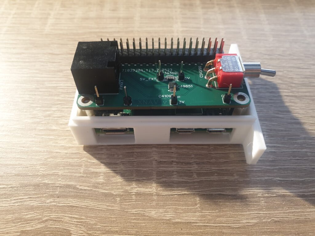
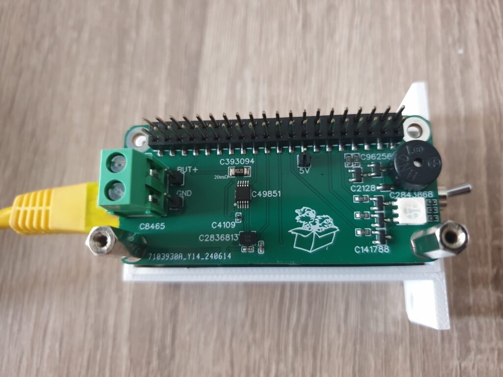
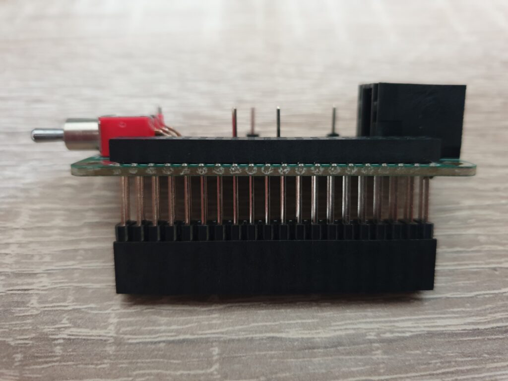
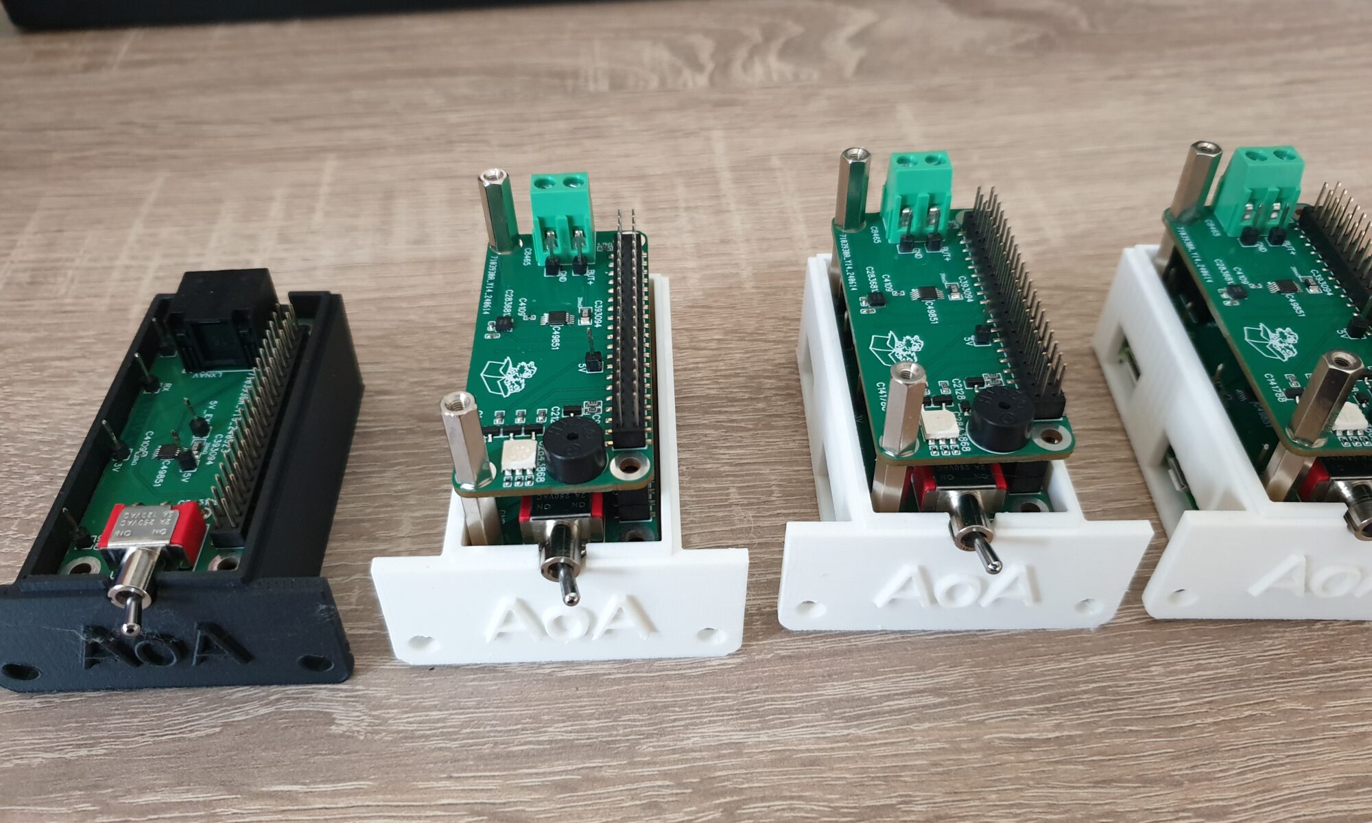
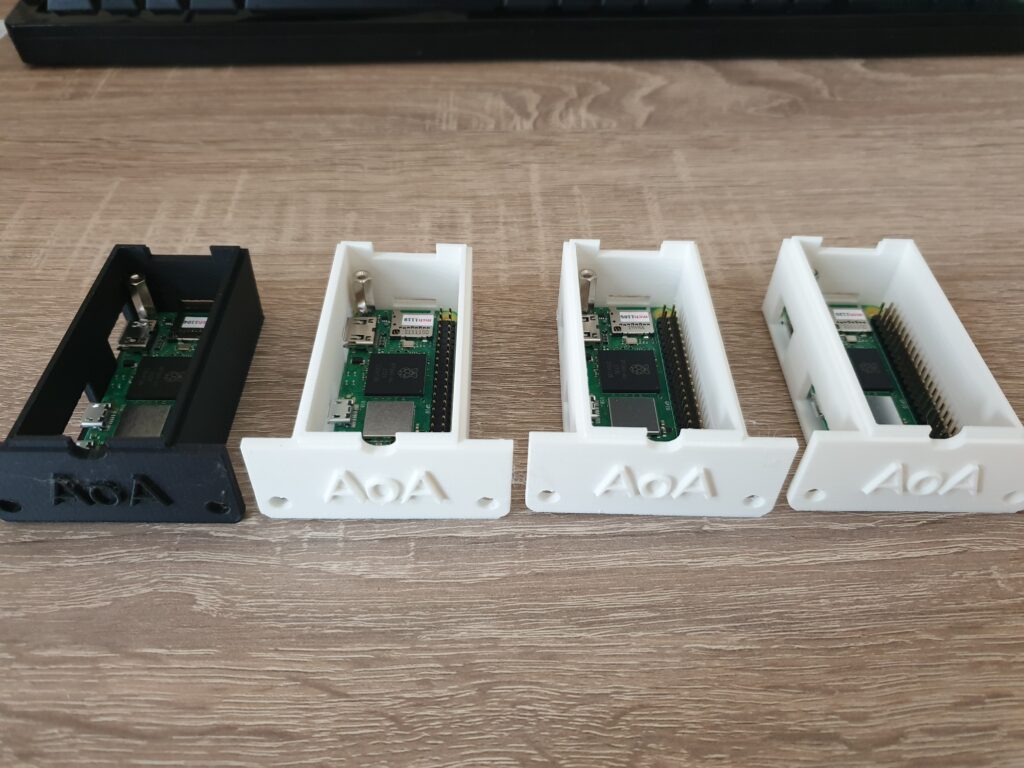
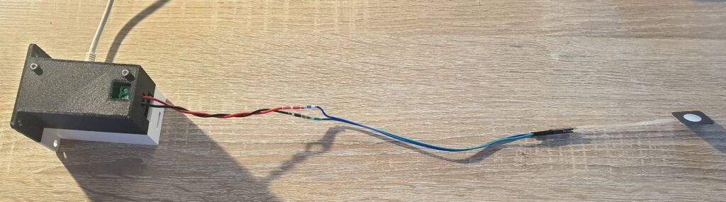
This is all the reason behind some of the decisions that I took over the last years. In project Hobbes I chose not to use a micro-controller and create a single-purpose device. I chose to use a Raspberry Pi Zero 2W, a massively overpowered device for the task, so I can change the device and run experiments without being even slightly bothered about performance. The device updates over the air, such that changes can be made quickly. The device is so overpowered, that I can perform most tasks in software. This allows a great deal of flexibility and keeps the hardware also very simple.
For my current glider this means that I’m working to get the instrument panel as empty as possible, and develop a control system (for the non-certified parts of the glider) that allows rapid experimentation. After all, there are a lot of questions left unanswered about what a glider pilot actually needs and how we can best interact with the pilot during flight. The system is designed in a highly modular way and will be (like Hobbes was) very overpowered for what it needs to do.
Conclusion
The pilots who flew with Hobbes weren’t wrong to complain. They were experiencing the logical consequence of a design tradition that never questioned its own assumptions. Every instrument added to a cockpit adds another voice asserting its own partial picture of the world — and the pilot pays the price. The way forward isn’t to add better instruments. It’s to build a cockpit that thinks. That’s what I’m doing.