

Last time I wrote about the things I did to close the feedback loop. I used an old PC with Condor Soaring to test the system, and I ordered an enclosure.
Results from Condor Soaring
My tests with Condor Soaring gave me a few interesting results:
- The system generally works as intended.
- One Indicated Airspeed update per second is worth testing, as long as I have 10 updates of the acceleration per second. This enables testing on LX8000/LX9000 devices, which my club has in their gliders.
- The system keeps on beeping after landing, and during take-off. This is very annoying, especially during the early phase of an aero-tow.
- The system lacks support for inverted stalls.
- My “let it crash” approach to software (inspired by Erlang) works and allows the system to recover gracefully from bugs. It does not restore the current maximum Angle of Attack, so I need to make that persistent.
Airspeed/Accelerometer
In order to allow me to work with LX8000/LX9000 devices, I need to have an accelerometer on board. After some pondering, I decided to make it an accelerometer/gyroscope combination in order to re-use this PCBA to create an IMU in the future. Due to the massive amount of smartphones that get built each year, there are loads of devices on the market. I decided to go with the Bosch BMI-270. I have good experiences with devices from TDK Invensense, such as the MPU-9150 and the newer ICM-20948. The latter however, works on just 1.8 Volts and wants to communicate with 1.8 Volt signals. This requires level shifters to and from 3.3 Volts. This means extra components and extra chances for making mistakes. I’m still learning about PCBA design off course.
So I decided to go the the BMI-270. It is more resilient against fluctuations on supply voltage than other alternatives and it appears to be quite stable. For what I’m currently doing it is probably overkill, but combined with the uBlox ZED F9P GPS modules I have lying around it might make a good IMU.
Beeping after landing
This problem was easily solved. When the derived angle of attack exceeds 1.25 times the maximum, the system becomes quiet. Using Test Driven Development, I wrote tests for this case, implemented the code and everything worked. Condor confirmed that it worked fine.
Inverted stall
The code was expanded to keep track of both a positive maximum Angle of Attack and a negative angle of attack. Depending on the acceleration that we sense, we compare the derived Angle of Attack against either the positive of the negative maximum. Again, using TDD I wrote the tests for this, implemented the code and tested it using Condor. It works fine.
Persistence
Whenever the system records the maximum Angle of Attack, be it positive or negative, it writes a file to disk with the values of both positive and negative maximum Angle of Attack. When the system starts it looks for that file and configures the values read from disk. Together with the restart mechanism I use, this makes bugs caused by transient phenomena a lot less annoying.
Enclosure
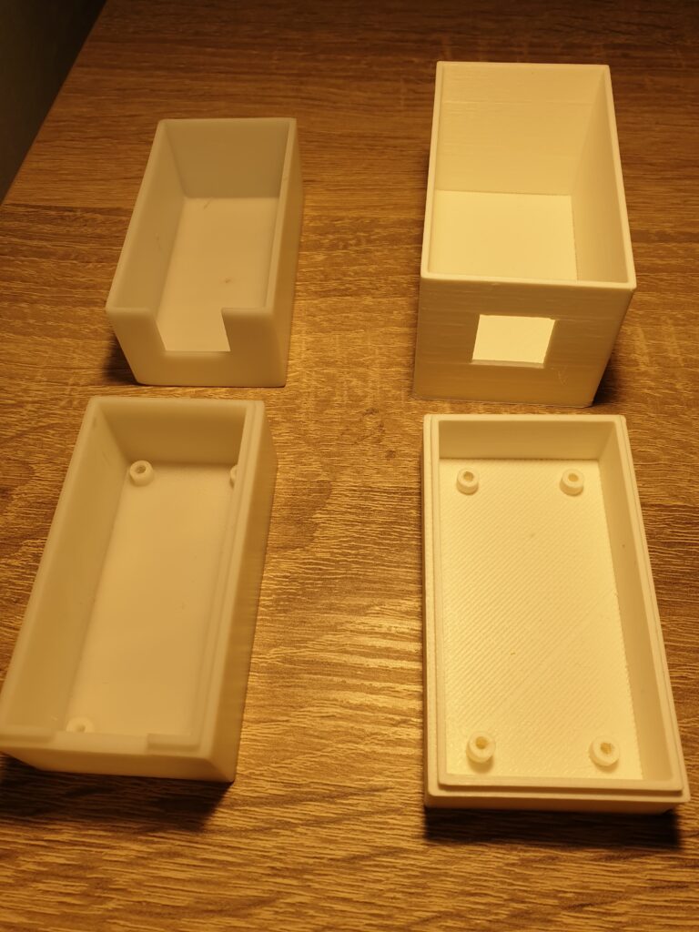
I ordered my first enclosure from JLC3DP. It was printed in SLA. I know this technique from a previous employer and I like how the results look. The surfaces a smooth. The first iteration cost me about $20 and took a week to arrive. I thought that this was a bit slow, so I turned to 3D Demand, a Dutch supplier or 3D printing. They were able to ship in 2-3 days for the same price (using PLA). This is not as smooth as SLA, but does the job for now. My first two enclosures both had errors in them, so having a quick feedback cycle is important for me. I want to get this right fast in order to start testing fast.
Hobbes

A friend suggested that the project really needs a name. We decided on Hobbes. I decided to adopt a logo for it too.
New Output PCBA
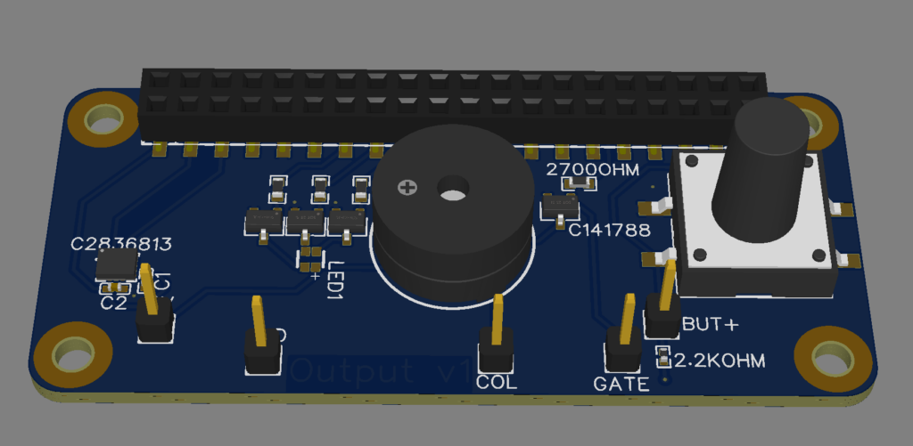
Since I have got something working, I’m looking towards simplification a little bit and towards the real-life tests in August. For this, I’ve ordered a new version of the Output PCBA with a few new aspects. Learning is the biggest goal here.
The first addition is the already mentioned BMI-270.
The second addition is an RGB LED. This can be seen in the center of the PCBA, just left of the Buzzer. This LED will hopefully mostly be off, but can use colors to indicate several error conditions.
The buzzer in the center has also been changed. Where I used an active buzzer, which generates it’s own 3kHz frequency when you apply voltage to it, I now switched to a passive buzzer. This requires the software to generate the 3kHz frequency. Using PWM I can also make the buzzer generate other tones. The Raspberry Pi has hardware support for PWM, which should make the tones accurate. Turning the buzzer on and off is now something I have to control in software. Some measurements on the timing the Raspberry Pi’s GPIO system indicated no more than 1 millisecond of delay and not more than 0.5 millisecond of jitter. I don’t think this will be noticeable in practice, so I decided to go with it. Should the need ever arise to generate different tones, then I’m prepared for it. I can even play entire melodies if needed.
The push-button was made taller. I really want to get rid of this button, since it requires a hole in the enclosure and it is hard to verify if it is still working. Due to the mechanical nature of the component, I can’t think of any ways to verify that it actually works. Instead I would like to see if I can use the accelerometer in the BMI-270 to detect “taps” on the enclosure as button presses. It is much easier to detect if the BMI-270 is still working and I need it anyway. It is also much smaller, and removing the button means less components that can silently fail. A challenge will be to accurately separate “taps” from turbulence or rolling on a rough surface. This is why I will keep the button until I am sure it’s obsolete.
I have made my first glider flights, and I’m looking forward to test this device in a real cockpit. This should tell me if the EMC that I’ve been warned about is a real issue, and if the power consumption of the device is low enough. I also look forward to seeing if the 80 dB speaker is loud enough during aerobatics. And I’m off course looking forward to the unexpected lessons I’ll learn from using the device in a real flight.
One Reply to “Towards an Audio Angle of Attack Indicator – Part 6: appearances”
Comments are closed.