
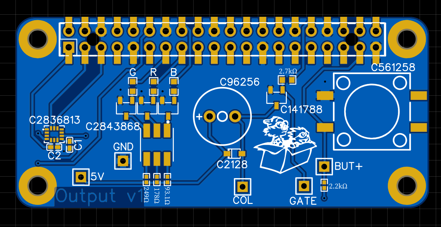
Last time I wrote about the next iteration of the Output PCBA. The PCBA features the first I2C IC, the Bosch BMI270. A passive Buzzer instead of an active one, which should allow me to produce different tones if users request that. And finally an RGB LED, which should give me the opportunity to convey errors to the user.
Long story short: this PCBA was kind of a failure. The RGB LED was fried on first try, and the buzzer didn’t produce any sound. I also made some minor mistakes with the BMI270.
Reflection
This was the trigger for some reflection. When I started to design this PCBA, I caught myself thinking: “I am getting the hang of this. Let’s try to make bigger steps, and let’s make progress without asking for help. That’s too slow.”. I felt greedy, rushed.
These feelings are not new to me. Due to my inherent sense of urgency, this is a trap that I’ve stepped into quite a few times already when creating software. Where in more bureaucratic processes, I often have to wait on others, I find myself to be the bottleneck more often in Agile processes. This is not a bad thing, but something I have to learn to deal with. In making software, the thoughts involved are usually something like “This code is so simple that I don’t need to test it, let alone write tests in advance (as TDD prescribes).”. Which is inadvertently followed by the humble lesson that my code doesn’t work and that I’ve attempted to go too fast. I need to take a step back when I feel impatient and come back when I’m calm enough to follow the practices that I know work well.
The overall lesson, in both software and hardware, appears to be: slow down to speed up.
RGB LED
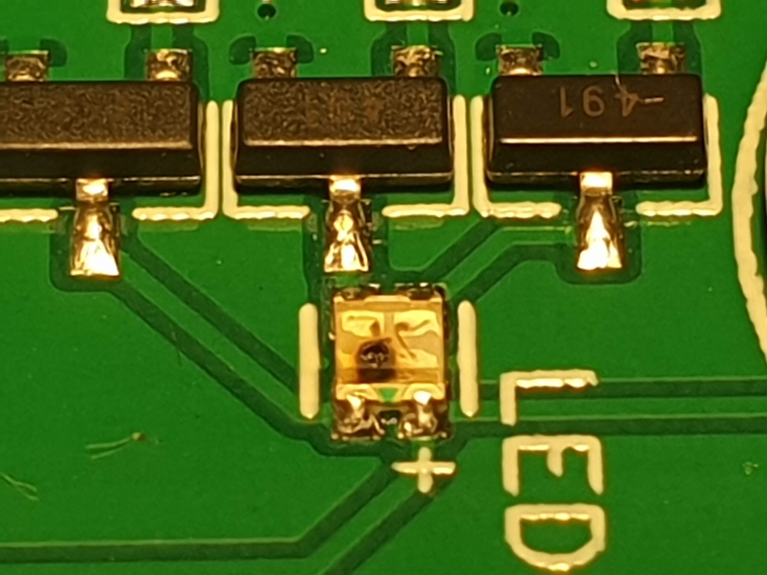
Back to what I screwed up and how I fixed it. The RGB LED had a datasheet…in Chinese. In my rush to complete something, I didn’t translate the datasheet and ended up mistaking the maximum reverse voltage (5 Volt) for the maximum forward voltage (around 2.4 Volt). The values for the maximum forward voltage differ per color, but the Red component has the lowest value. As a result that component burnt out immediately. Not knowing what happened, I tried to measure what was going on and had to conclude that everything worked as intended. Then I noticed the black marking on the LED itself. When I took unused PCBAs out of the box, I got what happened. I looked up the datasheet, translated it and got what happened.
Despite being able to fix this LED, I did conclude that the amount of light coming off the components was not enough for me. The intention is to illuminate the PLA housing from the inside, giving it a glow. This all has to happen in bright sunlight, so it needs to be bright. Power consumption is not my biggest worry here, since I will only turn on the LED in case of errors.
In an attempt to make all three LED components equally as bright (450mcd), I took some time to precisely calculate the needed resistor values for the PCBA. Not because the project requires it, but to show myself I understand this part of the design well.
Passive Buzzer
I expected the passive buzzer to work the first time, since I had already tested a passive buzzer on a breadboard. The setup was slightly different, as I didn’t use an NPN-transistor to toggle it, but I figured that my code worked and I had already used the same transistor for the active single-tone buzzer that I used in previous iterations.
Since my new buzzer was a passive version and thus does not include it’s own oscillator, I figured I wouldn’t need a flyback diode like I ended up needing for the active buzzer (remember the voltage spikes I wrote about earlier).
The buzzer only made small clicking sounds. Measuring what happened, told me that everything up to the NPN-transistor worked as expected, but the voltage levels around the buzzer made no sense and hardly correlated with the ON-OFF switching of the NPN-transistor. I was genuinely puzzled. My kind colleagues gave me some pointers on how they would connect he buzzer. In the end though, I ended up going back to the basics again: the datasheet. I found that I again had mistaken the maximum reverse voltage for the maximum forward voltage. I had picked a 30 Volt buzzer instead of a 5 Volt version.
So I replaced the 30 Volt buzzer with a 5 Volt version, and made sure that the datasheet also includes a application circuit. The circuit included a 1N4148 flyback diode I already used.
IMU – Bosch BMI270
I was genuinely excited about using the BMI270, since it is relatively expensive ($3 per PCBA) but has a good reputation among drone pilots. It is my first I2C device in this project, and thus a nice experiment to see if I understand the I2C bus on the Raspberry Pi enough to talk to it. According to online sources, no pull-up resistors are needed, so wiring was easy.
The BMI270 also has a downside: it is one of the few IMUs that needs to load firmware before actually working. Before loading this firmware, one can identify the device but not much more. The firmware is a whopping 8 KiloBytes large, which is kind of large compared to the 12 bytes that I normally read or write to I2C devices.
I was happy to see the device on the I2C bus immediately, and got to work with the “quick start” procedures in the datasheet. This worked more or less, except for the actual loading of the firmware. I got a very generic “Remote I/O error” from Linux, but a quick search online taught me that you have to send the firmware to the device in 32-byte chunks. That worked just fine, and after increasing some settle times beyond the datasheet values I was able to read accelerometer values.
One thing that I forgot with this device, is to attach the two interrupt lines that it features. These might save me some time and effort, since the device has a built-in step counter. The device might be able to interpret any “taps” as “steps” and thus give me an interrupt if a pilot taps on the device. Since I was already creating a new PCBA, I attached those two lines.
Enclosure
For the enclosure I ordered a third iteration. This was not intended to be production-ready, but instead to find the right diameter for the PCBA supports. In the first iteration, which was printed in SLA, I could have the m2.5 screw self-tap into the material. SLA appears to be somewhat elastic, which I suspect makes this possible.
The second iteration was printed in PLA, which appears to be less elastic. With the same diameter, self-tapping was not possible.
I went down a big rabbit-hole here to see what would be nice. My goal is to keep part-count as low as possible and make assemble simple too. Whenever I can use parts for multiple purposes at once, I would like to.
I decided not to use inserts that you have to melt into your 3d printed part, or tap threads into the 3d printed material. Instead I opted for mounting the PCBAs and securing the two halves of the enclosure with the same screws. This means the enclosure has counterbore holes on both sides, so I can use the m2.5 spacers I already have for both attaching the PCBAs and keeping the enclosure together.
This time I’m taking my time before ordering. I am getting closer to actual testing, so there is really no need to rush things. Slow down in the short term to speed up in the long term.
One Reply to “Project Hobbes: Part 7 – Failure”
Comments are closed.