Ever since I started my studies in Computer Science, I started to fiddle with electronics in gliders. I enjoy this very much, except for one small part: explaining this to other glider pilots. Most glider pilots I meet roll their eyes when I passionately talk about electronics in gliders, and mumble something like “But why?”.
Getting a bit tired of trying answer that question, I started to look online for like-minded people. And so around 2010 I found out about Idaflieg, the umbrella organisation of the German Academic flight clubs (Akafliegs), existed. Following their motto “Forschen – Bauen – Fliegen” (Researching – Building – Flying), they not only teach you to fly. They also perform research and build their own prototypes, quite successfully. It’s no surprise that most well-known glider manufacturers employ former Akaflieg members. Their prototypes also inspire these manufacturers. Perhaps the most recent example of this is the Mü31, whos influence can be seen on the high wing position of the Jonkers JS3.
Idaflieg collaborates with the German Aerospace Laboratory (DLR), which provides their beautiful Discus 2c DLR with instrumentation and personnel during the yearly summer meeting, the Sommertreffen. During 3 weeks, Idaflieg and DLR collaborate at Stendal airport to measure the performance and flight characteristics of gliders, perform their own experiments and certify their prototypes.
Visiting the Sommertreffen was on my wish list for about 10 years now, but I somehow never got around to it. Around new year of 2023 it started to hit me: I have to visit this event! No more postponing, this is the year. And so I drove via my club’s summer camp in Wilsche to Stendal.
The first night, I start to talk with Carlos of Akaflieg Stuttgart. He asks me who I am and why I am visiting. I expect the “why” question, but it doesn’t come. Carlos starts to tell me about his club’s project: fs36 – the first certified glider with fly-by-wire technology. Carlos tells me it’s pretty difficult, because none of the CS-22 regulations are written with fly-by-wire technology in mind. Therefore it’s up to Carlos and his club to prove their system is safe enough to be certified.
Zachering
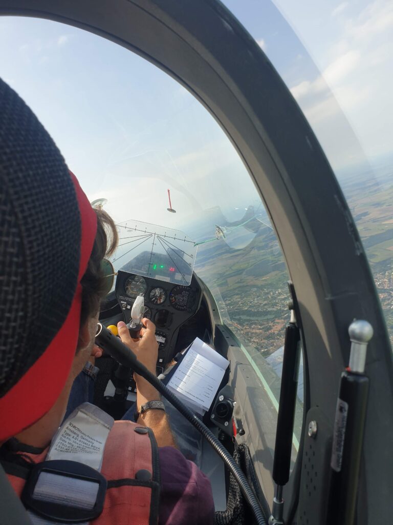
The next day I receive my instruction in Zachering, a systematic method of evaluating the handling of gliders named after it’s original author: Hans Zacher. By flying prescribed maneuvers and using just a stopwatch, tape measure and protractor, one can evaluate many aspects of a glider’s handling. Carlos asks me to join him in the evaluation of a brand new DG-1001 Neo, an offer I can’t refuse since I regularly fly aerobatics on the DG-1000S with 18-meter tips. My club has the “old” 20 meter tips too, and I don’t like them.
We tow to 1800 meters and retract the electric landing gear. First we look at the stalling behavior of the glider. We stall the glider straight and level, with 10 degrees of side-slip and in a steady 30 degrees turn. I notice that the DG has become more docile with these new tips, especially compared to the old tips I don’t like. There are lots of warnings before the glider stalls, and with 10 degrees of side-slip there is a tendency to enter a stable turn with some shaking and mild rocking.
Next up is the behavior related to adverse yaw. We roll a few times without using any rudder input and note for the time needed to reach 30 degrees of bank. We also estimate how much yaw is introduced as a side-effect of rolling. We also perform the inverse maneuver; from a stable 30 degrees turn we roll back to wings level using just the rudder. Finally we measure the time to perform a 45 degrees left to 45 degrees right turn. The DG seems more agile in 20 meters than I’m used to. I’m starting to be impressed with these new tips!
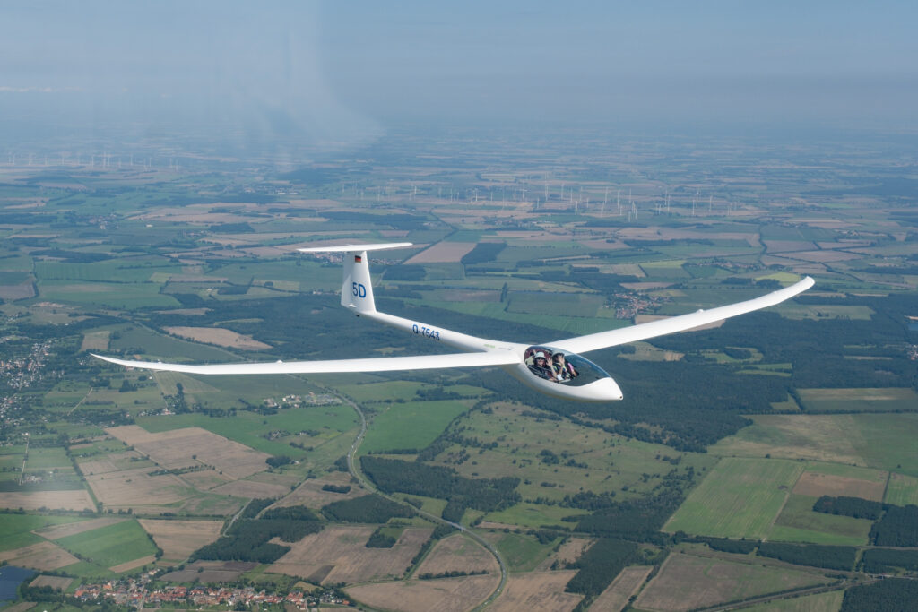
We enter a thermal together with the Akaflieg Darmstadt D-43, a side-by-side two-seater. The D-43 looks sleek when it flies over the iconic church of Stendal. Again I’m surprised by the low control forces of the DG.
The next day we continue our program. Next up are maneuvers to determine the stability of the aircraft, which requires still air. We begin with the dynamic stability in the pitch axis. After we release the tow, the DG is trimmed to 115kph and slowly decelerated to 100kph. After the stick is released, the aircraft enters a phugoid. The DG dives down and lifts the nose up at 130kph. I start my stopwatch and Carlos writes down 130kph. The DG slows down and lowers the nose, and Carlos writes down the minimum speed. The DG picks up speed again, accelerates to about 130kph and starts to lift the nose again. I time 27 seconds and Carlos writes down the airspeed. We continue this 6 times, and conclude that since the speeds at the top and bottom of the oscillation do not diverge the DG is currently dynamically stable in pitch.
Finally we look at the forces needed to fly different airspeeds. While having the aircraft carefully trimmed at 115kph, we fly different speeds and note down how much force should be exerted to steadily maintain that speed. We also look at the required stick deflections.
After about 40 minutes we’re done with the program and land. Next up is an evaluation of the cockpit and checking our results with an experienced Zacher instructor. If our results are good enough, they will be entered into a central database. Using this database one can then compare our results of the DG with the results from other gliders.
Performance measurement
After evaluating the DG with Carlos, I help with preparing a Glasflügel 304 for performance measurements. This particular 304 has been measured already once in 1981, but using a different reference aircraft. Measuring it again can reveal differences between the two reference aircraft and their setups.
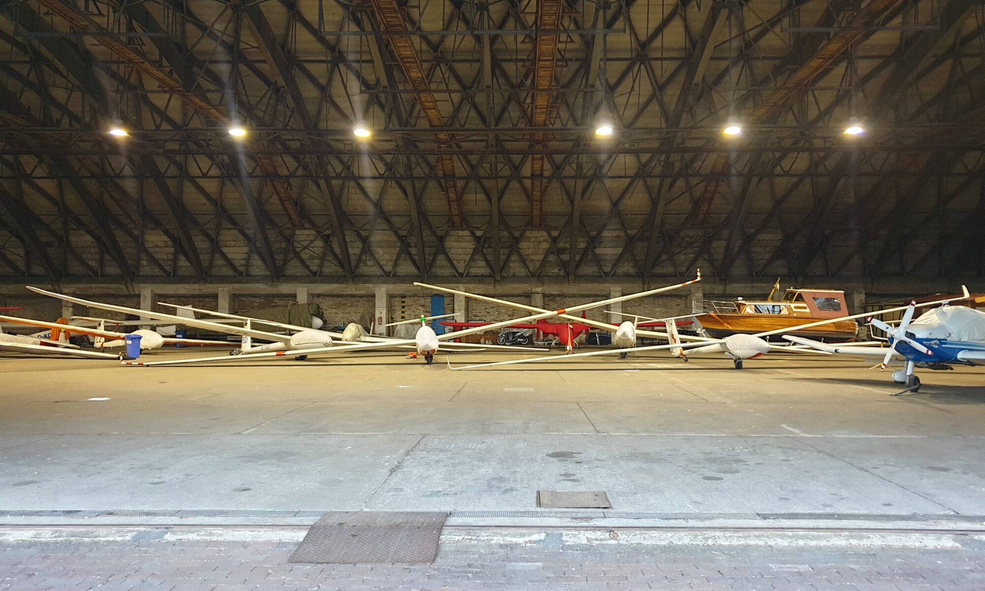
A complete day is spent cleaning, polishing, documenting (every little scratch and bubble in the gel coat is carefully described), instrumenting and finally weighing the glider. At the end of the day the 304 has been fitted with a very precise GPS received and a WiFi connection for communication with the reference plane. The plane is weighed with the pilot on board and parked in the front of the hangar.
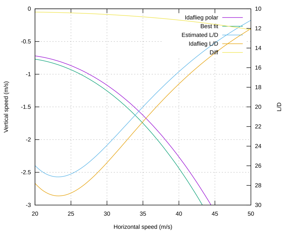
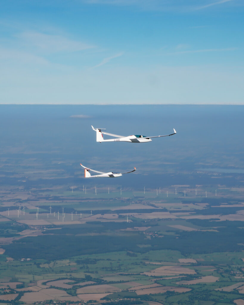
The next day my alarm clock goes of at 05:20AM. This is when the decision is made: is the weather favorable for a turbulence-free performance measurement? The weather looks good, and at 05:45AM the Discus 2c DLR, the Glasflügel 304 and two tow planes are transported to the runway. Everything is set up on the runway of Stendal and the tow planes tow the gliders to 3000 meters. To prevent the pilots from getting bored, quality German music is played over the radio. The gliders are towed into formation and release. For each data point, they fly the same airspeed for a few minutes in formation. Meanwhile the measurement system records their vertical speed precisely at 10 times per second.
After about an hour the gliders fly over the airfield in formation and land. A DLR employee starts to extract the data from the Discus 2c DLR. He shows me a plot with the measurement from 1981 and today’s measurement. The data looks good: as expected there is a slight degradation in performance compared to 1981.
After a week I drive home extremely inspired. I’ve learned a lot, I’ve seen lots of awesome prototypes (more on those in separate posts) and I’ve even been able to help a little bit. I can’t wait for next year…