Last time I wrote the challenges I faced with different types of equipment. Because different types of equipment provide me with different supply voltages, different UART signal levels and event different power supply polarities – I decided to introduce modules.
IGC Input Module
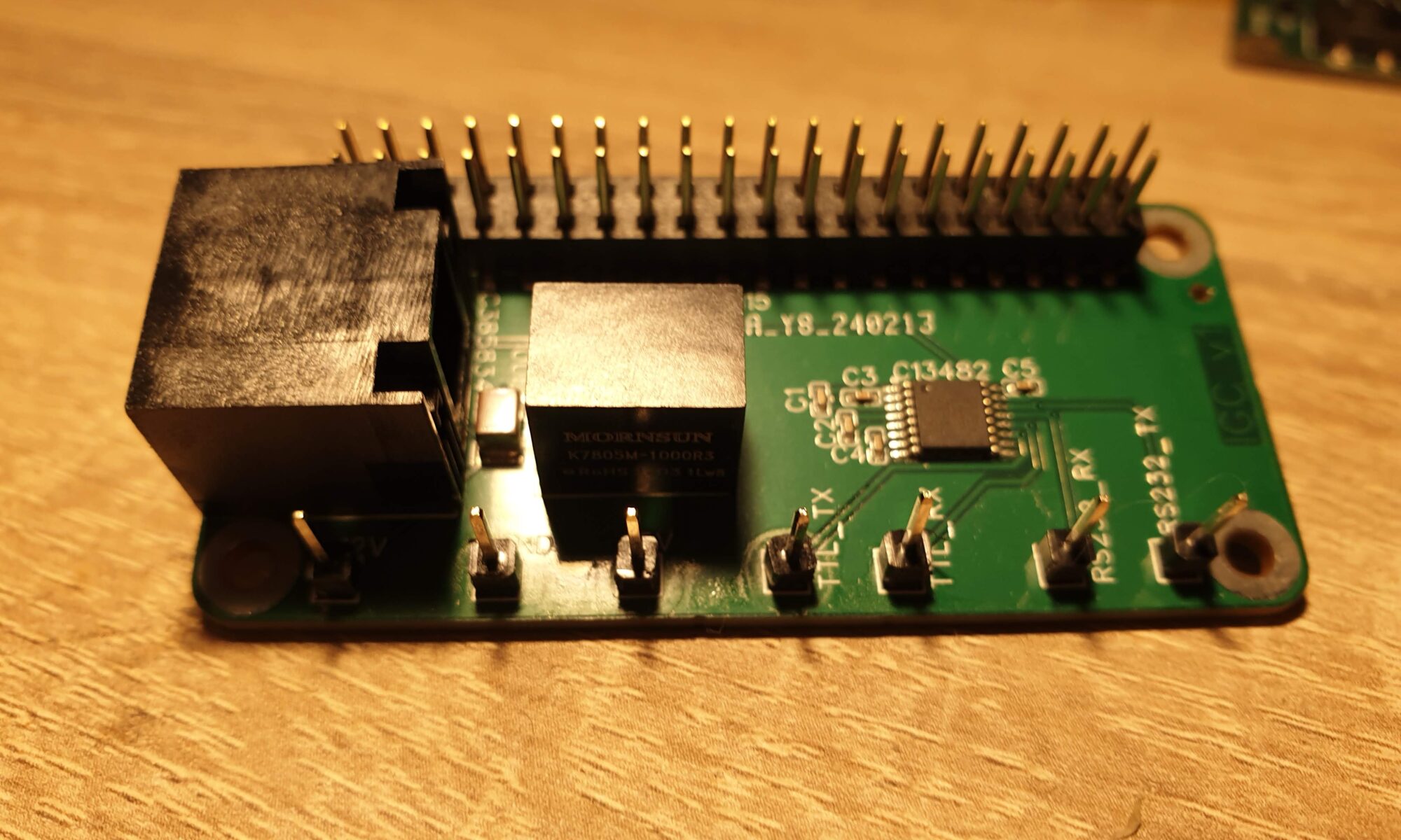
The first module PCBA I ordered was a new Input Module, one that deals with the standard IGC RJ45 pinout. It converts 12 Volts to 5 Volt for the Pi and translates the Pi’s 3.3V UART signal levels to the standard RS232 signal levels of approximately 10 Volts. This was exciting for me, since this was the first time I was doing something more significant than connecting stuff with traces and maybe a resistor here and there. The MAX232 Chip that I used needs a bunch of capacitors to perform its task. The 12 Volt to 5 Volt converter that I used also needs capacitors to work. I now have multiple voltages running over one PCBA: 12 Volt, 5 Volt and 3.3 Volt.
To my delight, everything worked as expected. In order to learn about unit testing for hardware, I wrote a bunch of tests. I can now verify the properties of the DC-DC Converter automatically, using just my Korad KA3005PS programmable power supply and my Hantek 6022BL USB scope. Here is a movie of the test running:
Later on I also verified that the MAX232 setup is working as expected. I have let some friends review my PCBA layout. I’m starting to get more and more confident about creating PCBAs. Even the quality issues I encountered last time, where JLCPCB had placed the wrong part on some of my PCBAs, is now gone. They did have a question about the holes in my PCB being defined two times, so I fixed that.
Now what?
After I verified that this board was working well, progress was slow. There are a lot of things that I can do, but not a lot of things that I have to do. I’m starting to get closer to my initial goal of having hardware that works. So what now?
Last time I mentioned EMC compatibility, fault handling and an enclosure. The enclosure felt useful, but was a bit scary because I have no experience in 3D modelling. EMC is a potentially expensive excercise, but might be important if my enclosure doesn’t block EM radiation. Fault handling feels almost like an academic exercise at this point, and I lack the experience to analyse faults properly.
So perhaps I should just keep doing what I did so far? Improve the PCBAs?
For the Output board, where the buzzer and push-button are currently located, I wondered about placing an RGB led for status indication. It might also be nice to have an accelerometer on the board, which allows me to connect my device with any LX8000/LX9000 device. My gliding club has their entire fleet outfitted with these. An accelerometer might even replace the push-button, if I can use tapping gestures on the device. This makes the device simpler and allows me to make a simpler enclosure. I have not yet gone through with this, because I wanted to test the gesture detection first and see if the 1Hz indicated airspeed that the LX8000/LX9000 devices give out is good enough to give a shot.
I wondered if upgrading the Input board for the LXNAV devices with a current shunt and INA226 current sensor might be a good step forward. This would be a first step towards fault detection and fault tolerance.
Closing the feedback loop
While the above things are nice, they do not bring my system closer to reality. After some thoughts, I decided that the system needs to face reality as quickly and as often as possible. Instead of refining the system over and over based on my idea of what is “better”, I have to face the unforeseen stuff that real-world usage brings.
So I decided to step away from PCBA redesign for a bit and focus on other things. I installed Windows 10 and Condor Soaring on an old iMac I had lying around. This allows me to test my system at home. Condor Soaring is capable of sending out the exact values my system needs at 10Hz. This allows me to fly with the system at any time I like.
Testing the system with a simulator brings many interesting lessons. I can no longer start the software myself. What happens when (part of) the software crashes? I’m finding lots of small issues and questions arise.

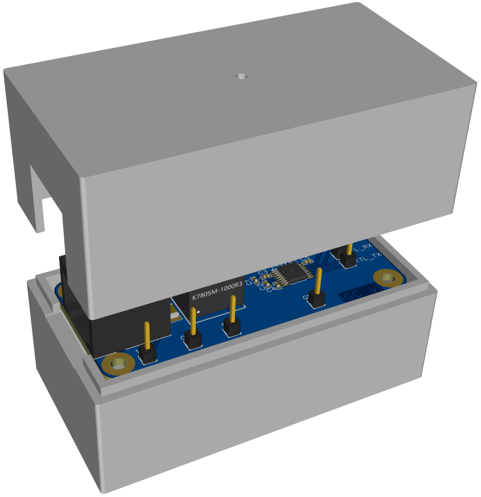
Another thing I did was design and order my first enclosure. EasyEDA Pro has a tool that lets you design an enclosure quite simply. I can then order that enclosure at JLC3DP. It should arrive in about a week from today.
Now that the gliding seasons got started and that I have actually booked my visit to this year’s Idaflieg Sommertreffen in August, I’m eager to start testing my hardware in real life. I can’t wait to use the system and learn more.


One Reply to “Towards an Audio Angle of Attack Indicator – Part 5: closing the feedback loop”
Comments are closed.