Last time, I wrote about some ground tests I did and the preparations I made for a refactor. In the past two weeks I’ve been able to refactor the project’s enclosure quite a bit, thanks to my preparations in OpenSCAD and my friend Roald, who owns a 3D printer..
First Enclosure
At Aero Friedrichshafen I learnt that the device should really be mounted in the instrument panel, in either a standard 57mm hole or in a standard 80mm hole using an adapter. So, as part of the “Test Driven CAD” efforts I made, I modelled the adapter-plate with screws and made a test make sure my neither the PCBAs nor the enclosure interfere with it.
I was very keen to prove to myself that this “Test Driven” bussiness has the potential for me to get things right the first time. TDD has been a massive improvement in my productivity as a software developer, so I was hoping to get similar improvements in working with CAD. I wasn’t disappointed…
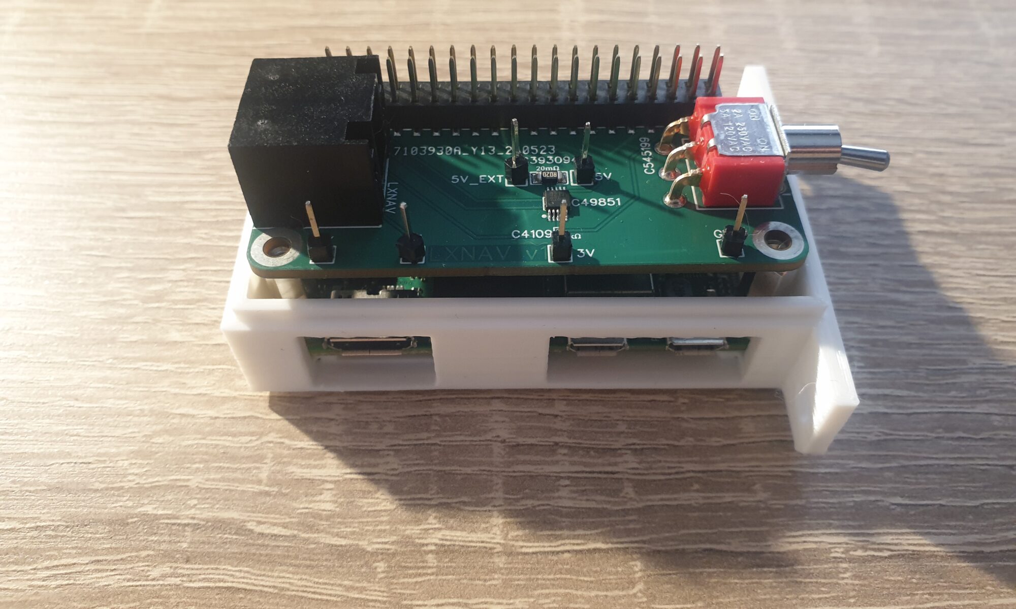
First I added “ears” to the enclosure, such that it can be mounted in a standard 57mm hole. After I spent countless times inserting and removing the Raspberry Pi Zero 2W from the bottom of the enclosure, I decided to add some holes for the ports I use: micro-USB for power, USB-OTG for keyboard/mouse and HDMI for display. I also added a hole in the enclosure through which I can (for now) press the PushButton that’s on the Output PCBA.
Full of confidence I sent Roald a bunch of STL files…and he told me things were not okay. The top and bottom showed overlap and could not be mounted together, and my PCB support pillars on the bottom of the enclosure were too thin to actually print.
I implemented a test to verify that top and bottom do not overlap, and made some changes to get it right. For the PCBA support pillars, my CAD drawings were telling me that there is a conflict between the Raspberry Pi’s pin header and the support pillars (more specifically: the counterbores in the support pillars). I realized that I really don’t need counterbores near the Pi’s pin header, since the stack of PCBAs provides more than enough rigidity due to the pin header stack itself. So I removed the entire set of standoff screws on one side of my PCBA stack and solved the issues with the PCBA support pillars entirely.
I pushed my code to the CI/CD server and collected a set of checked STL files, forwarded it to Roald and waited. The next day at the airfield I received a new version of my enclosure… talk about quick feedback!

I was very pleasantly surprised by this enclosure. Everything fit inside as planned, I could close the enclosure and mount it to the adapter-plate. Apart from a small miscalculation for the HDMI port, everything worked exactly as intended. Test Driven CAD was a success! I quickly grabbed my laptop and fixed the HDMI issue. To the next version!
Registration at Idaflieg
Around this time it was time to officially submit my project to Idaflieg, so it can be considered for this year’s Sommertreffen in August. I was asked to describe my project, it’s goals, what I’ll do with the results…and potential safety risks. Using some of the experience I’ve recently gained on this topic from my workplace, I saw some potential risks that could drastically increase pilot workload. Not good. It was very clear to see that one solution would answer them all without a doubt: a hardware On/Off switch. Up to now I had always wanted to do everything in software, but it is beginning to dawn on my that you have to account for buggy software.
I finished the Idaflieg form and submitted it, and immediately started to redesign my Input PCBA to contain a hardware On/Off switch. Since the switch should penetrate the enclosure at the front, this also means changing the enclosure (adding a hole at the right place). I found out that my PCBA was too far away from the front of the enclosure to make the switch actually usable by the pilot. So it was time to really test my CAD skills now and reduce margins around the PCBA stack to 0.5mm and make an additional hole for the SD-card to stick out. This was all done in CAD, and I kindly asked Roald to print a new version of the enclosure again.
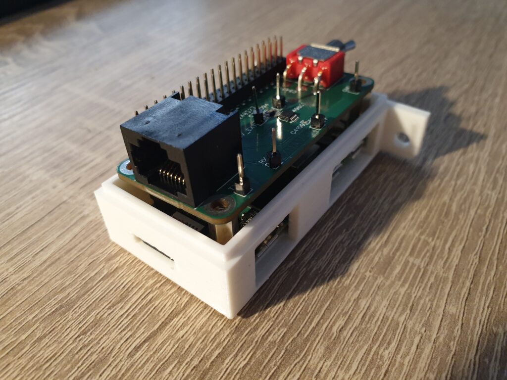
Both the new PCBA and the enclosure arrived at the same day. I put in the Raspberry Pi, and saw that everything fit perfectly. This was a really proud moment! The hole for the On/Off switch was exactly at the right place and the SD-card also aligned perfectly. The only issue was…the switch now prevents me from sliding the entire PCBA stack inside the enclosure. Not totally unexpected, but something that must be fixed in the next iteration.
The PushButton
I was really struggling with the wish of having the PushButton mounted on the stick. Since there is no standard shape or even diameter for sticks in gliders, I found it difficult to come up with something that will work reliably with very little effort or customization. So I started to ask around.
Not only does Roald own a 3D printer, he also possesses the kind of hands-on creativity that I often envy. Things just come to him in a way that I can’t replicate. When I met Roald at the airfield, he showed me this:
These booklets are just a few euros, and contain about five of these membrane pushbuttons with flexible PCBs attached to them. I got one of them, and opened it up:
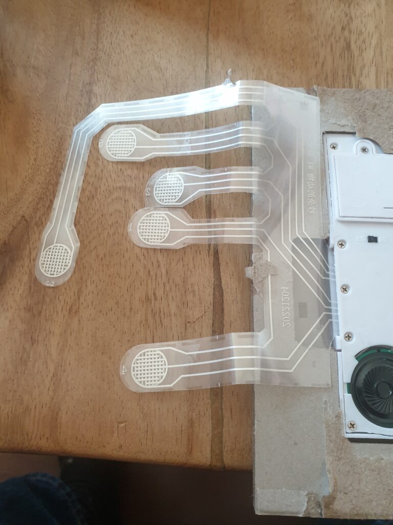
It contains membrane buttons. They can easily be mounted to anything with a bit of tape or even some Velcro. After a bit of googling I found that there also exists a similar technology called metal dome buttons, and ordered of of those:
I think this might work well, since it can be mounted on the already-present Zacher tape measure mount. It provides tactile feedback as requested, and can easily be installed or removed. The flexible PCB attached to it appears to be strong enough, although the DuPont connection at the end still requires some thoughts.
I am extremely pleased with the amount of progress that I have been able to make in just two weeks. This was accompanied by a feeling of playfulness and flow, which seems a good indicator of being on the right track with eXtreme Manufacturing. Next up is getting the PushButton right, and perhaps starting to write the pilot’s manual.
One Reply to “Project Hobbes: Part 10 – Mechanics”
Comments are closed.