
Last week iteration 2 of my PCBA arrived in the mail, just a week after ordering. There is a lot of good news, and some disappointments…
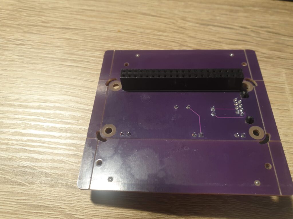
First things first. This is what the bottom of the PCBAs look like. There is a 2×20 row of female headers on the bottom, ready to be placed onto the Raspberry Pi’s pin header! For an additional $100, I selected the more elaborate PCBA service with parts placement on both sides from JLCPCB. That means no more soldering for me, and ready-to-use PCBAs right in the mail. This is a bit expensive for my taste, but for the time being it enables me to iterate on my design faster. I will probably move to female SMD headers on the top, which should accomplish the same thing without the hefty pricetag.
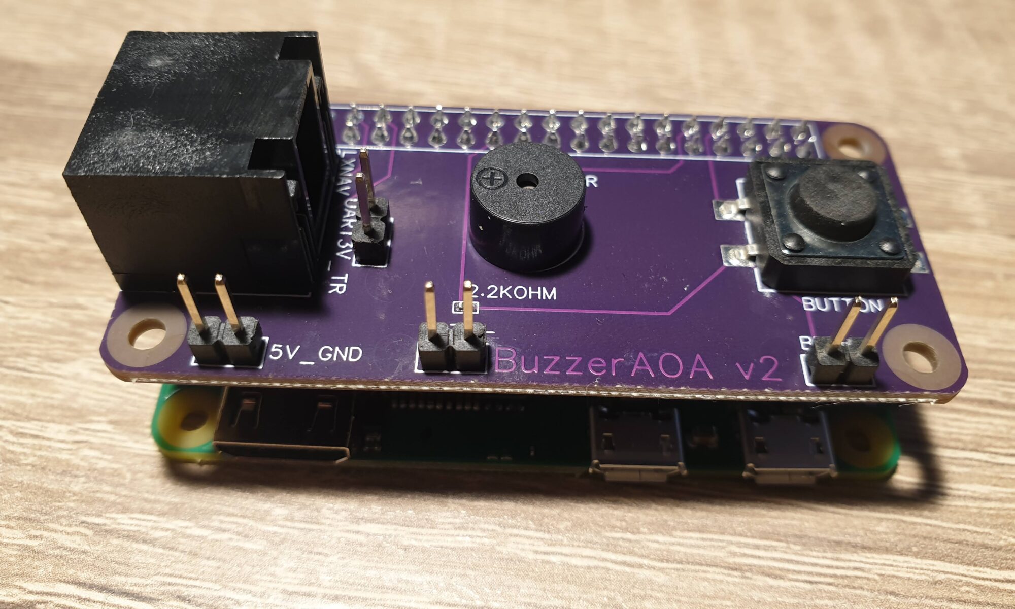
The PCBs are now 4 layers thick, with Signals on the outside layers (for easy modification when I make errors) and a 5 Volt and Ground layer in the middle. These planes make save me a lot of individual tracks for 5 Volt and Ground, which makes routing a bit easier. The tracks that I did have to place, I placed such that they are always visible and easy to remove if I make a mistake.
After ordering this iteration, I had some doubts about the buzzer pulling so much current (30 mA) that the Pi couldn’t supply it properly. At first this seemed to be confirmed by my Hantek 6022BL Linux-supported USB-scope, which showed just 2.5 Volts on the pins. Further investigation seems to indicate that it’s actually the scope that’s at fault here. A normal multimeter shows the expected 3.3 Volts. The buzzer also uses less than the 51 mA that the Pi should be able to supply on all of its GPIO pins combined.
It still makes sense to look into powering the buzzer from the 5 Volt plane, using a transistor of some sort to toggle it. After talking to some wise men around me (you know who you are), I decided to re-design the circuit a bit and use an NPN-transistor to toggle the buzzer. I also considered a MOSFET, but that was overkill and introduced the need for voltage divider circuits. I want to keep things as simple as possible, and the NPN-transistor is as simple as I can make it right now.
For the next version I’m thinking about introducing an RGB-LED to communicate the software status to the user. I figure this might be useful when things don’t work as expected. Such a LED uses around 20mA per color, which makes using transistors good practice.
Back to this iteration… After the board arrived I quickly checked if things work as expected. The debug pins are very helpful for this, although it would be better to place them further apart. I have no need for connectors, and the ground-clamp on my scope is so big I’m running the risk of creating shorts. Also, it makes no sense to duplicate Ground pins everywhere.
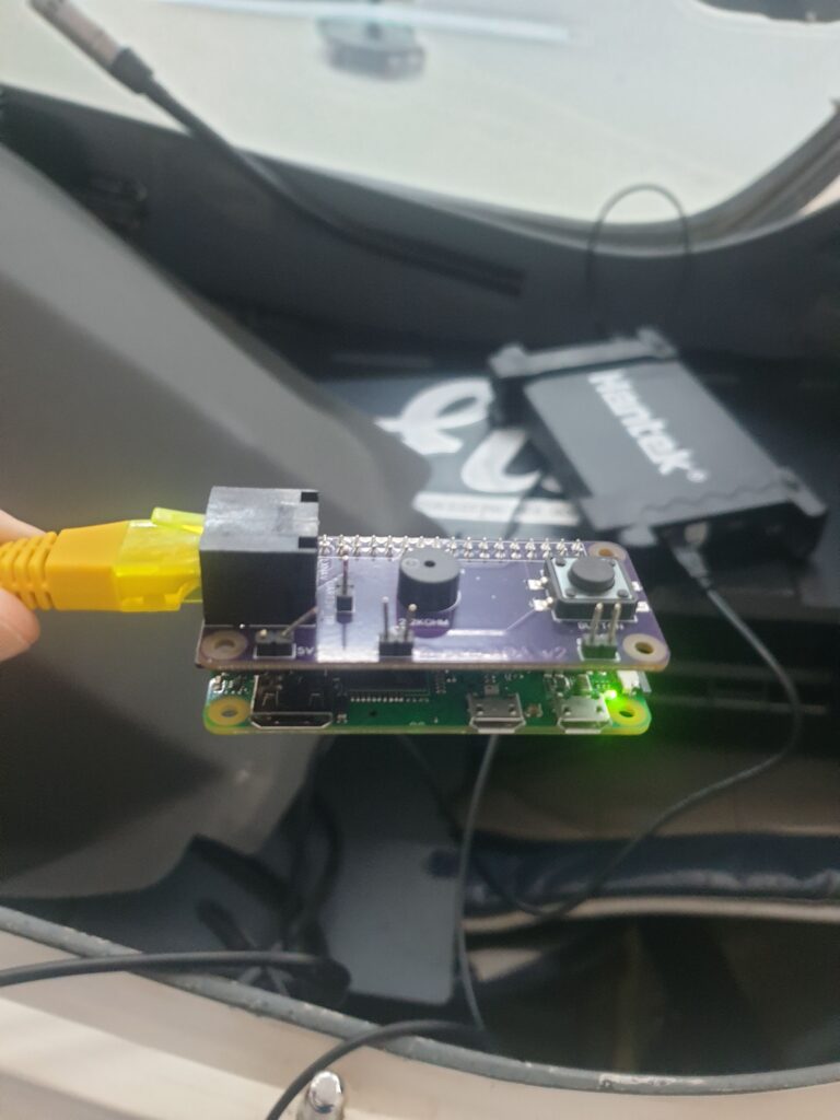
The board works and the Pi boots fine with it. The button now works as intended and the buzzer still works. So then it was time to take the board to my gliding club and test it with real hardware!
The RJ45 pinout seems completely correct! That is a big win for me, since I’m always struggling with pinouts. Matters were not any better this time, as even the numbering of the pins was non-standard in the LXNAV manual. I’m pleased I got it right the first time. The Raspberry Pi Zero boots without a problem using the 5 Volts from the LXNAV, and it can receive the NMEA data from the LXNAV. Progress!
Software
A mild disappointment was finding out that only the S-series variometers from LXNAV support the particular feature I’m using. I assumed from the specification that I had read that any modern device from them would export the needed values (G and IAS at 10Hz). This turned out not to be true. From a first glance at the LX Navigation dataport specification, it should be possible to get the correct data from those kinds of devices. Hopefully the RJ45 pinouts match enough so I can connect to both.
All in all I am quite pleased at how far I have been able to get within a few weeks. I am especially thankful for all the help I have been getting and the encouraging messages I’ve received.
One Reply to “Towards an Audio Angle of Attack Indicator – Part 3: First tests”
Comments are closed.