
Last time, I wrote about the first PCBA being on it’s way. As I’m writing this, the second PCBA is on it’s way towards me. And boy, does it have a lot of improvements…
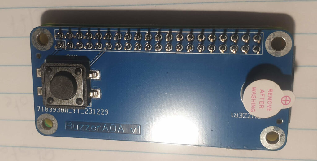
The first iteration was a “Hello World” of PCBA: it featured just a button and a buzzer. Long story short: the button didn’t work and the buzzer did…sort of.
As soon as the PCBAs arrived, I soldered one onto a 40-pin header and tested it on my least expensive Raspberry Pi: a Zero W. The Pi didn’t even turn on. That’s not good, but it still worked without my PCBA. Although my soldering isn’t that great, it wasn’t the cause for the problems I was seeing: all PCBAs had a short between the button’s terminals.
Button
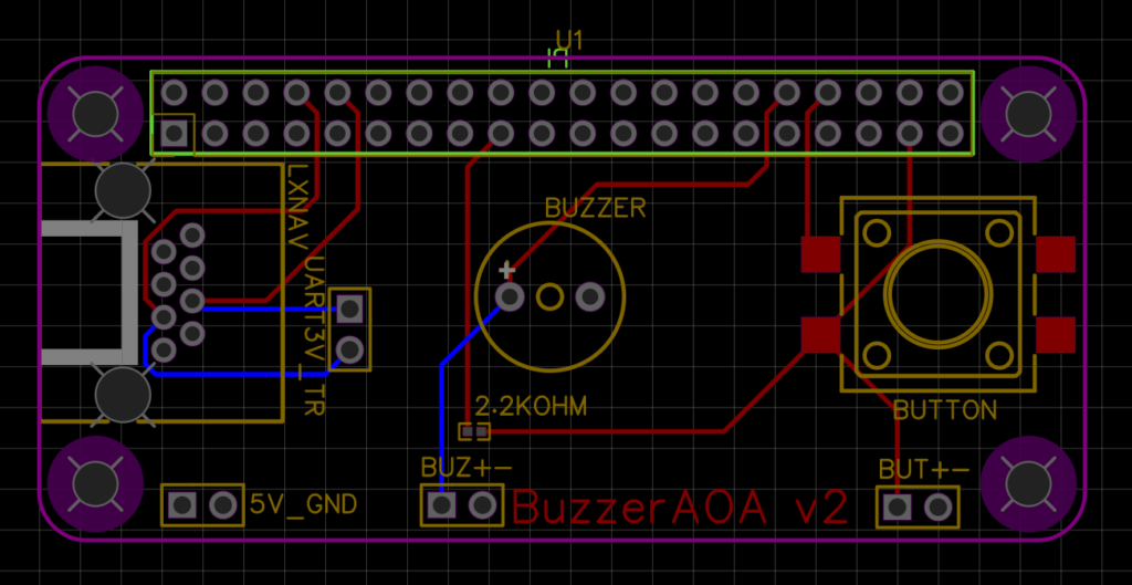
During design of the PCBA, I decided to tie unused pins from the button to ground. Not such a great move, since I created a short between the 3.3 Volt pin and ground this way. Luckily the Raspberry Pi Zero has some protections and just didn’t power on. No fried hardware yet.
It took me a while to figure this out, but once I did I could easily fix the problem by scratching through one of the lines towards the button. Now the button didn’t work at all, but at least I could test the buzzer.
Another problem with the button was the GPIO pin I had connected it to. Aparently GPIO pin 17 is sometimes used for other things, even though it’s not documented.
Buzzer
The buzzer worked! It made a sound and it was nearly loud enough. A good result for a first try.
What’s next?
First I created an Excel sheet to keep track of which pins I was using and what pins the other Pi HATs I own use. In the future I want to combine my PCBA with perhaps a 12-Volt powerboard and a 5-inch LCD screen.
I then fixed the short-circuit for the button, and started to look at the extra features for the next iteration.
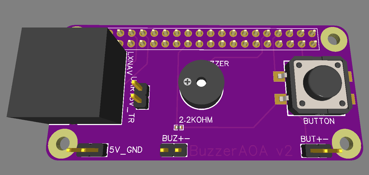
After spending way to long on soldering this PCBA, I decided to see if I could have the manufacturer of the board solder header on it for me. I turned it he can. A few hours of fiddling with EasyEDA later and the 3D view showed a PCBA with female headers attached to the bottom.
The next version should also contain debug points, so I can attach my USB-scope to the board and see what’s happening.
Last, but certainly not least, the board should receive power and data. Lucky for me, this is rather easy. I’m connecting my board to an LXNAV 9070, which delivers 5 Volts of power at a maximum of 1 Ampere. This is precisely what I need and the Pi Zero W can operate well below the maximum of 1 Ampere. The LXNAV also provides a UART interface at 3.3 Volts, which is precisely the voltage that the Raspberry Pi Zero W wants. Since the Raspberry Pi Zero already contains protection against static electricity, there’s no need to build in extra protections at this point. It’s just a matter of routing the correct pins from the RJ45 connector to the correct pins of the Raspberry Pi 40-pin header.
Now that I’m feeding the Raspberry Pi via the RJ45 connector, I’m starting to thing about all the wiring. I remember a former colleague mentioning 4-layer PCBs and I start to investigate a little bit and talk to my electrical engineering colleagues. I decide to create a 4-layer PCBA for the next iteration, just to see if it makes life more easy for me. At JLCPCB, who I use to create my PCBAs, it makes no difference at all if I use 2 or 4 layers… so let’s try it!
Both the UART and the 5 Volt circuits get their own set of pins for attaching a scope, and I order the next version of the PCBA. Since I decided to place parts at both the top (button, buzzer, RJ45 connector) and the bottom (female headers to save me some soldering), I now have to move to a more expensive price category…which is about $100 extra compared to the previous iteration. That’s definitely something I’m going to look at for version 3.
After ordering, I’m again faced with the long wait for these PCBAs to be made. Although the week it takes JLCPCB to manufacture and send the PCBAs is quite quick by modern standards, I’m so used to feedback loops measured in seconds or maybe minutes that this feels like going back in time. Despite feedback being somewhat slower than I’m used to, I’m quite excited about this small project. I’m learning new things every time I’m working on this project, and people all around me are very willing to teach me. No amount of studying beats experience…
One Reply to “Towards an Audio Angle of Attack Indicator – Part 2: Hello World”
Comments are closed.