Last time, I wrote about my happy experiences with Test Driven CAD, registration at Idaflieg and some adventures with the PushButton. When I write this, I have only two months left to my visit at the Idaflieg Sommertreffen, which doesn’t feel like a lot…especially if you take into account holidays and work. The good news is, I’m on final glide towards having at least support for the LXNAV S80/S100 variometers working.
Nerves
The doubts that creep up in my mind are all rooted in one thing: the lack of real-life testing. I’m starting to be convinced that this is where this eXtreme Manufacturing (agile) stuff helps a lot: you test early and often. I wish I could have tested more, and sooner. I have successfully tested a lot of software with the usual techniques (Mocking, Faking). That’s not where my doubts are. They are more centered around the stuff I can’t easily test: the entire Linux system I’m dragging along, the manual, etc…
Enclosure updates
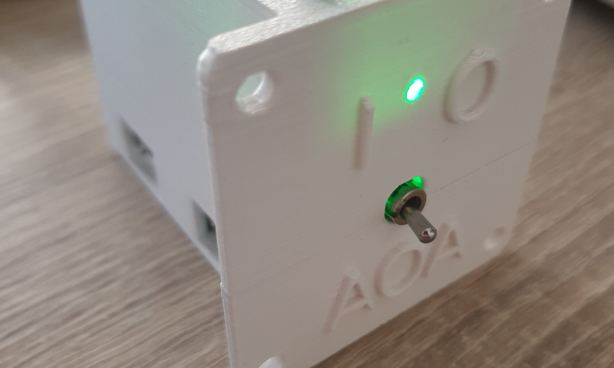
In the last version of the enclosure was a hole where the On/Off switch can go through. I just had trouble installing the contents into the enclosure. The fix was very easy: split the enclosure at the location of the switch instead of below it. I thought it would also be nice to have the positions of the switch be visible on the outside, so I added some text indications on the device, as well the text “AOA” to indicate what the device does.
This version of the enclosure is printed with ASA, which is supposedly more resistant to UV radiation and heat. The previous version was printed in PLA by Roald. For crash-worthiness, I verified that the enclosure can handle at least 6kg of weight. Since the device itself weighs almost exactly 100 grams, this is equivalent to 60G. Should be good enough.
Output PCBA
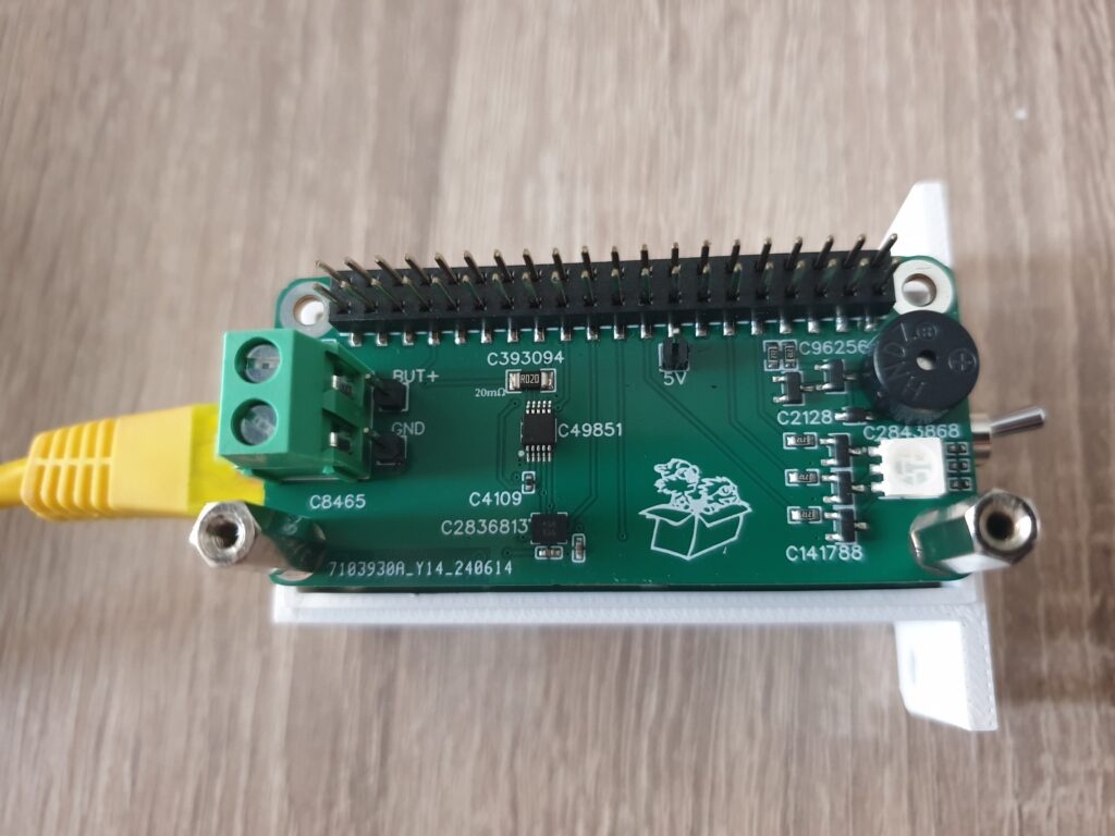
I’ve revised my Output PCBA quite a bit. With the realization that the PushButton should really be removed, I’ve investigated the method of connecting the PushButton to the stick and to the read-end of my device. Since the PushButton used to be placed at the very front of my device – and the connector is now at the very rear – I have had to change the Output PCBA quite a bit. The PushButton will be connected using old-fashion screw-terminals. I’ve looked at many connectors, only to realize that this solution is by far the most flexible.
The RGB LED is now located at the very front of the device, which should it good visibility to the pilot. The RGB LED will be used to indicate system status to the pilot. When the device detects it might malfunction, the RGB LED will turn red to indicate that the device should be turned off with the On/Off switch.
In the last iteration of the Output PCBA, I switched from an Active Buzzer (which generates a fixed tone at 2700Hz) to a Passive Buzzer (which can generate many tones, but needs a PWM signal to do so). I tried to see if turning the Buzzer on and off using software timers worked well. It more or less does, but sometimes the jitter involved in software timing becomes noticable. Realizing that I have two PWM lines available in the Raspberry Pi Zero 2W, I decided to use both: one for turning the Passive Buzzer on and off, the other one to change the tone. This means that I only need to tell the PWM hardware what to do and it will continue to do so forever. This also should reduce CPU usage a bit, and therefore power consumption.
PushButton
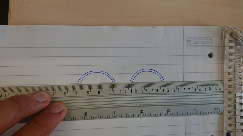
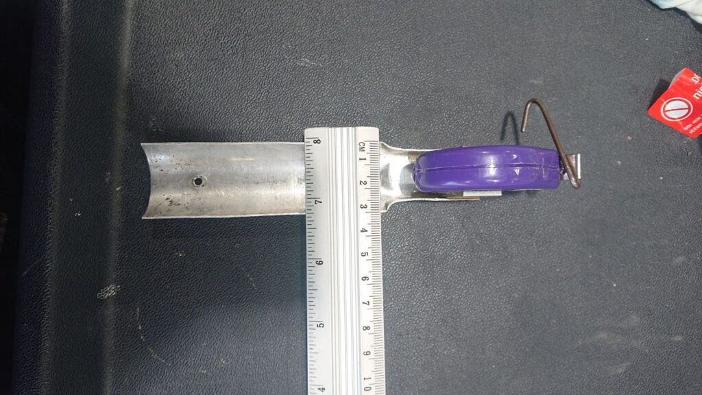
My current plan is to mount a Membrane Button on the measuring tape mounting on the stick. I’m no too sure if the button can nicely follow the curvature of the plate, so I will make a replica and test that. There is a Plan B: handheld pushbuttons.
Idaflieg Sommertreffen
I received the happy news that my project has been accepted for this year’s Idaflieg Sommertreffen! This means that up to 4 aircraft will be fitted with a copy of my Angle of Attack indicator, and the pilots flying those aircraft will provide me with feedback on the device. I’m both very excited and grateful to be accepted, especially since I’m not a member of an Akaflieg and there’s some funding involved. In return I will write an article (both here and in Idaflieg’s winter report), and I’ll present the results of the project in the next Wintertreffen.
Part of the feedback I received was to investigate if my setup falls within the standard changes as defined by CS-STAN. It appears to fall within the description of CS-SC062a: Installation of an awareness function or awareness device. This means I’ll spend some time to look at the recommendations and requirements outlined in this standard change, to make sure my device complies and perhaps revise the manual a bit.
Speaking of a manual… last time there was none. I have started to write one, also in an effort to detect any blind spots. I’ve also started to ask some Akafliegs if I can mount my device in their gliders.
Testing
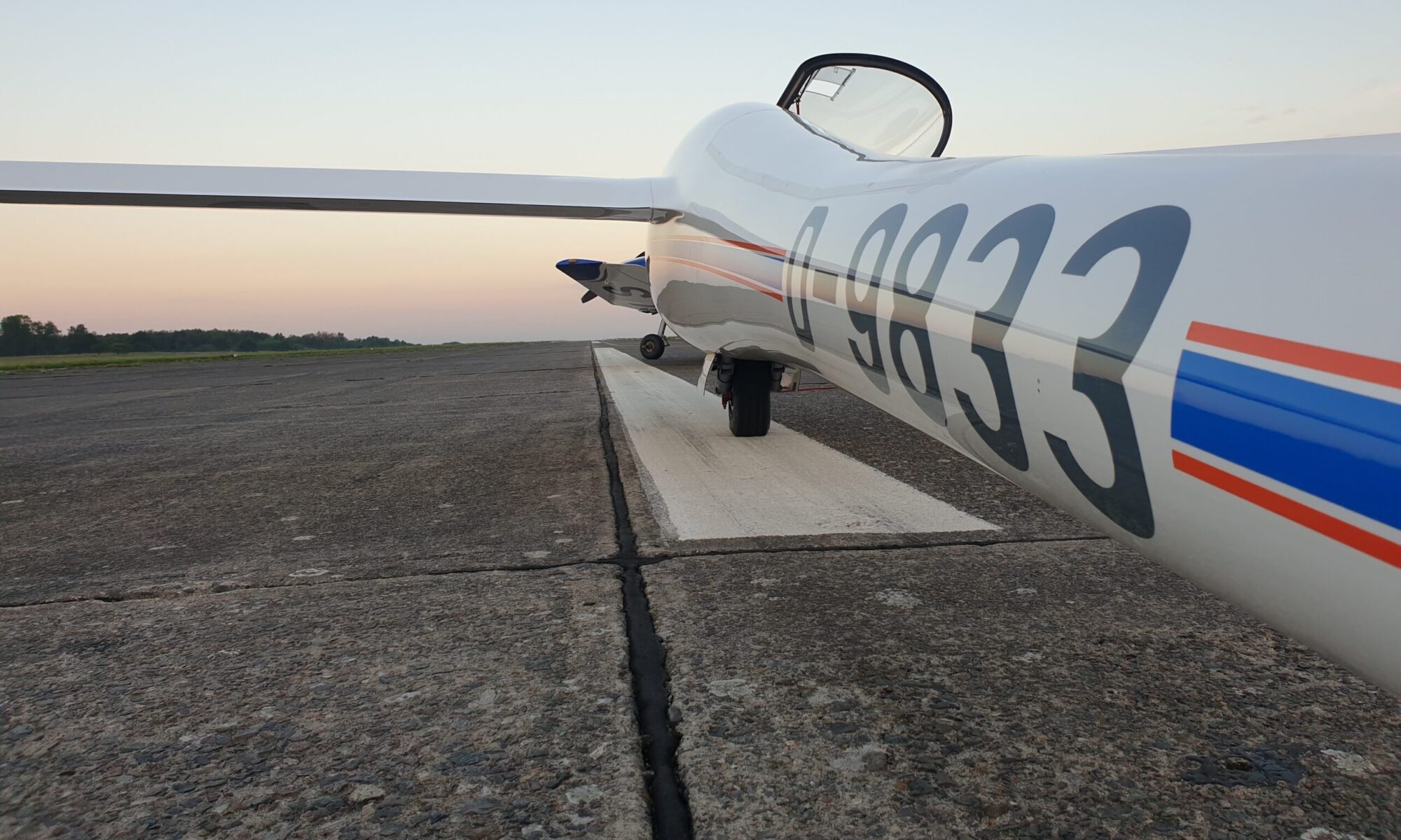
Since I’ve not yet had my device connected to an LXNAV S80, I’ve asked a friend from my gliding club if I can lend his Glasflugel Libelle with S80 for some testing on the ground. The Libelle is awesome in the sense that you can easily remove the instrument panel from the glider. So I spent some time with my friend’s panel…and everything worked right out of the box! That’s a huge confidence boost!
With the Sommertreffen approaching and approval to execute my project, I’m excited to get everything done. Most things are in place and work consistently. Some things, like the PushButton and the Manual need some attention. I intend to start series production a month in advance, so there’s probably one iteration left. We’re on final glide.
One Reply to “Project Hobbes: Part 11 – Final glide”
Comments are closed.