Towards an Audio Angle of Attack Indicator – Part 4: Modularity

Last time I wrote about some setbacks. The LXNAV devices that my club owns (LX8000 and LX9000 series), do not support the 10Hz data that I require. This has been the source of a major change in the project: the introduction of modularity.

But before I discuss this major step forward, I should describe iteration 3 of the PCBA.

Changes in iteration 3

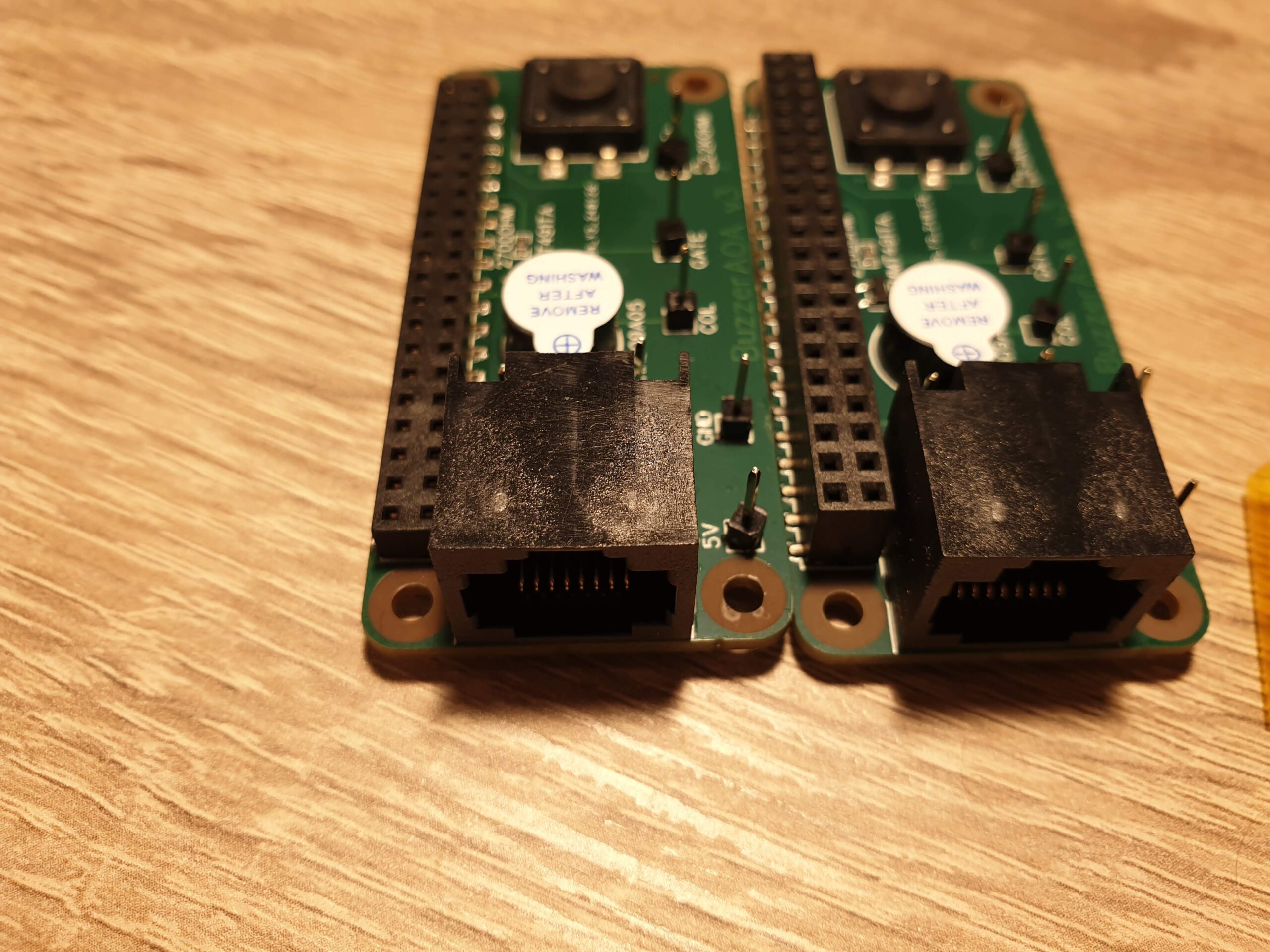
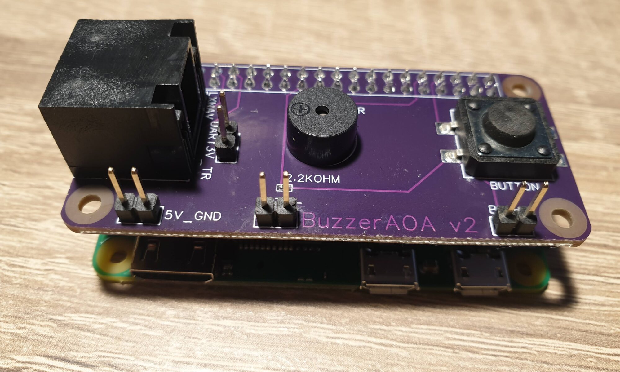
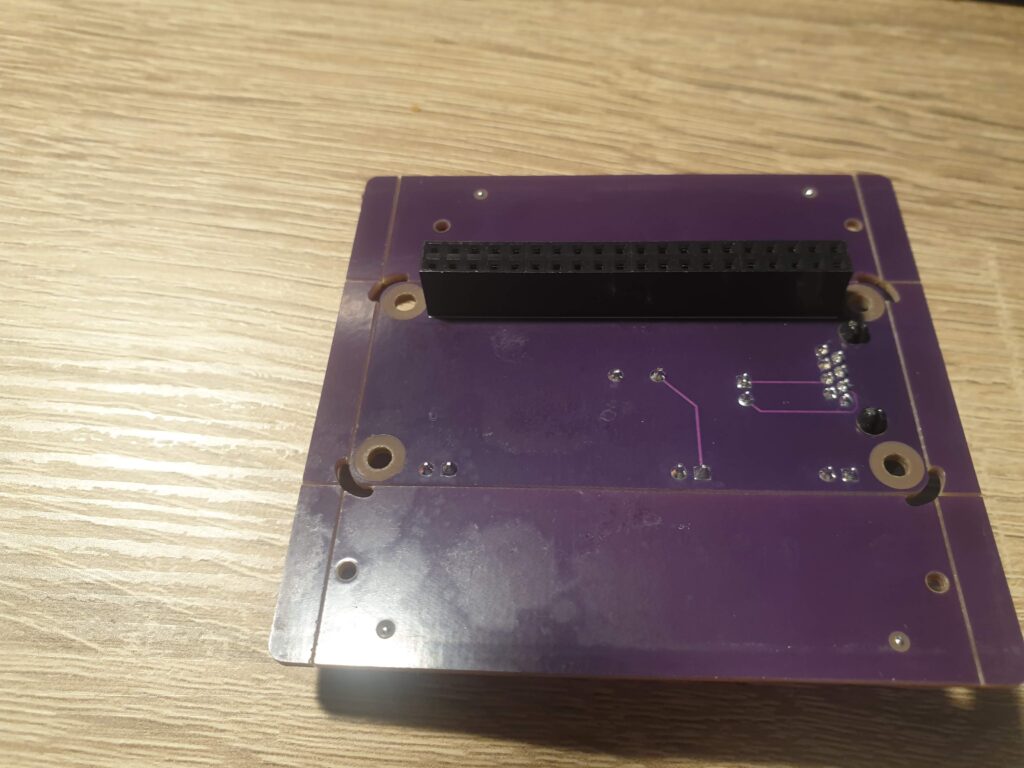
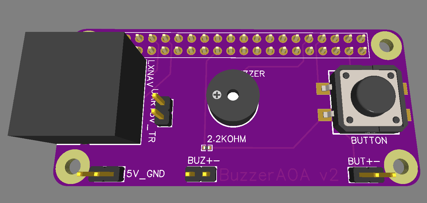
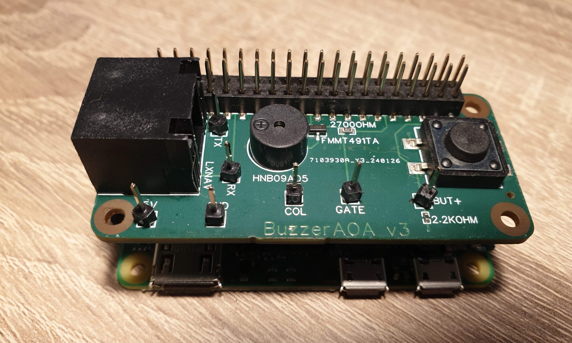
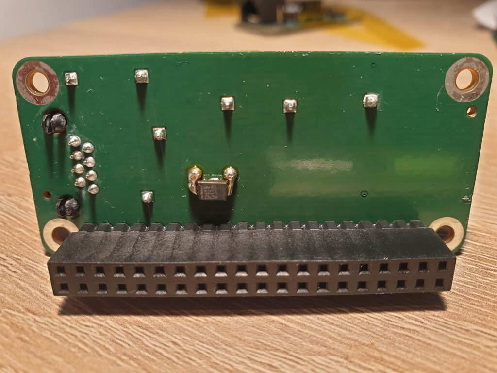
There it is. I replaced the expensive female headers at the bottom with female headers at the top. This saves about $50 per order and allows me to stack as much PCBAs on top of each other as I like. But as the picture shows, it was not easy for JLCPCB to select the correct part. Three of the received PCBAs received the tall female headers visible on the right, while two received the correct female headers visible on the left. I off course filed a complaint, which was handled very nicely. The next batch of PCBAs is on it’s way to me as I’m writing this, and I’m curious how they turn out.

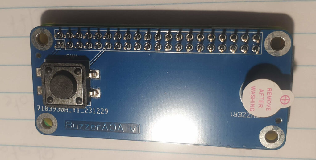
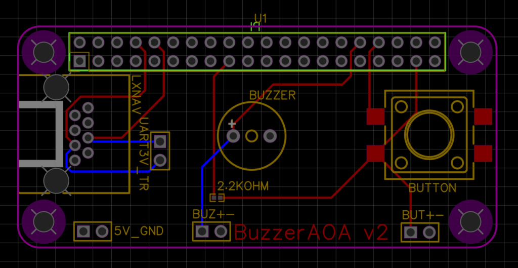
Another change is in the buzzer. As mentioned, the previous version had a 3.3V buzzer which was powered by the Raspberry Pi. Because the Pi can only supply a grand total of 51mA (at 3.3V) over all the GPIO pins combined, this solution wasn’t a very good way forward. Iteration 4 contains an NPN-transistor, which I toggle with the Pi’s GPIO pin. The transistor then allows about 200mA to flow directly from the +5V rails to the buzzer. Since the +5V rails is directly connected to the LXNAV device, I have about 1000mA available here. Much better than the 51mA of the GPIO pins!

This version also has the debug pins spaced more evenly over the board, because the lack of spacing was a hazard for shorting two pins in the previous version. The crocodile ground clamp on my scope is simply too large. I did not repeat the GND pin everywhere as well.

Buzzer changes for iteration 4

The spike and oscillation after turning the buzzer off. Yellow band is -5V to +5V

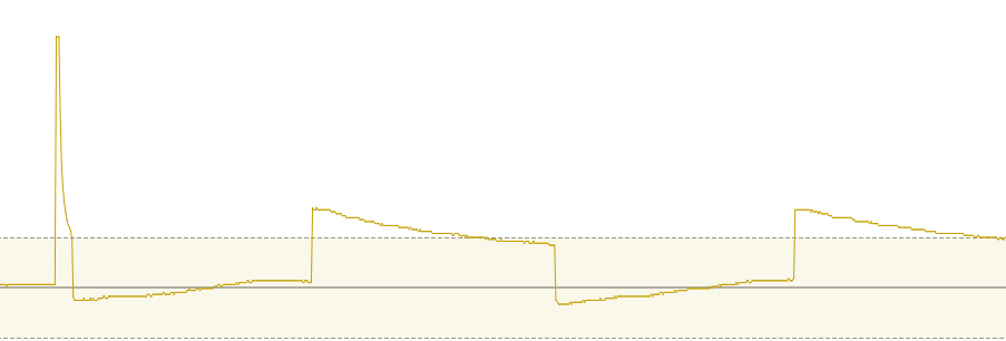
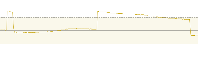
While testing iteration 3, I stumbled upon something that nobody really saw coming. When the transistor cuts the circuit between the Buzzer and GND, huge voltage spikes occur. They were clipped at 25V by my scope, and they appear to be periodic at about 2.2kHz and last about 15 milliseconds. This is suspiciously close to the 3kHz frequency of the buzzer. The electronic experts I consulted suspected it is the membrane of the buzzer which is still vibrating. A colleague was kind enough to solder a diode between the two pins of the buzzer, which should allow any excess current to flow to the +5V line. A quick check with the scope shows this is true: I see no spikes exceeding +7V now, which is great.

A diode soldered across the through-hole pins of the active Buzzer.
The same situation, but now with a diode placed across the buzzer.

Modularity

An example of stacking multiple HATs on top of the Raspberry Pi Zero. The new female headers on top of each HAT allow for an infinite amount of HATs to be stacked.

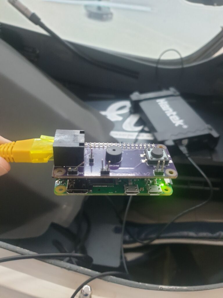
The last thing to address is the issues I noticed when testing iteration 3 in the workshop of my gliding club: our LXNAV devices don’t send out the data I require to operate!

This has several solutions:

  1. I am now actively looking for private owners who have a glider with an LXNAV S80 or S100. My current hardware should work with those devices, and it provides me with the data.
  2. I am creating a separate version to support LX Navigation devices.
  3. I am considering adding my own accelerometer and seeing if the 1Hz Indicated Airspeed as provided by my club’s gliders is enough to test the system.

Point 2, supporting LX Navigation devices, makes life difficult. Whereas LXNAV provides me directly with 5V and TTL-level UART data, the LX Navigation devices provide me with 12V power and RS232-level UART data. To make matters worse, their pinout is exactly opposite from LXNAV!

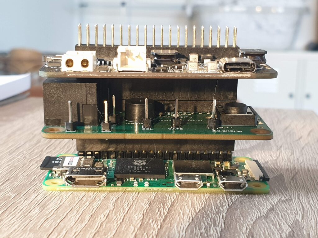
After a lot of considering, I decided that this warrants splitting my single PCBA into two separate PCBAs: one for input (UART and Power) and one for output (Button and Buzzer). I can then create two different Input modules – one for LXNAV and one for LX Navigation – and iterate the Output PCBA independently.

The two modules are stacked on top of each other, using the stacking mechanism that I introduced in Iteration 3.

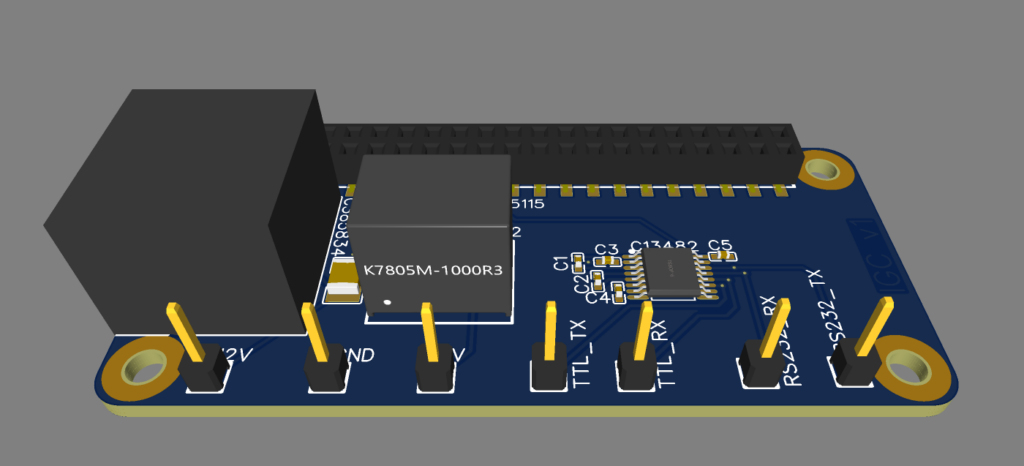
As I’m writing this, the first iteration of the LX Navigation Input Module is on it’s way to me. Since I now have to change the voltage from the 12V battery (providing anywhere between 9V and 18V) to the 5V that the Raspberry Pi requires, I have had to introduce a complete DC-DC Converter module. In order to change between RS232 voltage levels and TTL voltage levels, I have had to include a MAX232-like chip. It was a nice step up from the easier circuits that I had to make before. I’m eager to learn if I got it right. If everything works, this version should also be compatible with other devices that adhere to the IGC standard pinout, like LX Navigation does. That means it should also work with devices like the XCVario.

This is what version 1 of the LX Navigation Input Module should look like. RJ45 connector on the left, DC-DC Converter module in the center, MAX-232 on the right.

Future plans

As the hardware is getting more and more mature, there are some things that I still have not addressed…

I have not performed any ElectroMagnetic Compatibility (EMC) testing. This is something that I should really do before I the system in a glider. The device might otherwise interfere with other on-board electronics. Especially the radio is susceptible to interference in my experience.

I have not made any enclosure for the device yet. An aluminium enclosure might help prevent any EMC issues too. However, I am not yet skilled with 3D modelling. The PCBA design tool I’m using, EasyEDA, does include a 3D modeller for enclosures. Perhaps that is the easiest solution, as JLC also provides 3D printing and CNC services.

There is the aspect of fault detection and fault handling. I have not yet added the LEDs that I talked about last time.

Which brings me to perhaps the most important aspect: getting feedback. Despite all my talk about iteration, I still have to get my hardware airborne. I hope next month I will get the first user feedback.

Towards an Audio Angle of Attack Indicator – Part 3: First tests

Last week iteration 2 of my PCBA arrived in the mail, just a week after ordering. There is a lot of good news, and some disappointments…

First things first. This is what the bottom of the PCBAs look like. There is a 2×20 row of female headers on the bottom, ready to be placed onto the Raspberry Pi’s pin header! For an additional $100, I selected the more elaborate PCBA service with parts placement on both sides from JLCPCB. That means no more soldering for me, and ready-to-use PCBAs right in the mail. This is a bit expensive for my taste, but for the time being it enables me to iterate on my design faster. I will probably move to female SMD headers on the top, which should accomplish the same thing without the hefty pricetag.

The PCBs are now 4 layers thick, with Signals on the outside layers (for easy modification when I make errors) and a 5 Volt and Ground layer in the middle. These planes make save me a lot of individual tracks for 5 Volt and Ground, which makes routing a bit easier. The tracks that I did have to place, I placed such that they are always visible and easy to remove if I make a mistake.

After ordering this iteration, I had some doubts about the buzzer pulling so much current (30 mA) that the Pi couldn’t supply it properly. At first this seemed to be confirmed by my Hantek 6022BL Linux-supported USB-scope, which showed just 2.5 Volts on the pins. Further investigation seems to indicate that it’s actually the scope that’s at fault here. A normal multimeter shows the expected 3.3 Volts. The buzzer also uses less than the 51 mA that the Pi should be able to supply on all of its GPIO pins combined.

It still makes sense to look into powering the buzzer from the 5 Volt plane, using a transistor of some sort to toggle it. After talking to some wise men around me (you know who you are), I decided to re-design the circuit a bit and use an NPN-transistor to toggle the buzzer. I also considered a MOSFET, but that was overkill and introduced the need for voltage divider circuits. I want to keep things as simple as possible, and the NPN-transistor is as simple as I can make it right now.

For the next version I’m thinking about introducing an RGB-LED to communicate the software status to the user. I figure this might be useful when things don’t work as expected. Such a LED uses around 20mA per color, which makes using transistors good practice.

Raspberry Pi Zero booting with power from my PCB for the first time, powered by an LX8080.

Back to this iteration… After the board arrived I quickly checked if things work as expected. The debug pins are very helpful for this, although it would be better to place them further apart. I have no need for connectors, and the ground-clamp on my scope is so big I’m running the risk of creating shorts. Also, it makes no sense to duplicate Ground pins everywhere.

The board works and the Pi boots fine with it. The button now works as intended and the buzzer still works. So then it was time to take the board to my gliding club and test it with real hardware!

The RJ45 pinout seems completely correct! That is a big win for me, since I’m always struggling with pinouts. Matters were not any better this time, as even the numbering of the pins was non-standard in the LXNAV manual. I’m pleased I got it right the first time. The Raspberry Pi Zero boots without a problem using the 5 Volts from the LXNAV, and it can receive the NMEA data from the LXNAV. Progress!

Software

A mild disappointment was finding out that only the S-series variometers from LXNAV support the particular feature I’m using. I assumed from the specification that I had read that any modern device from them would export the needed values (G and IAS at 10Hz). This turned out not to be true. From a first glance at the LX Navigation dataport specification, it should be possible to get the correct data from those kinds of devices. Hopefully the RJ45 pinouts match enough so I can connect to both.

All in all I am quite pleased at how far I have been able to get within a few weeks. I am especially thankful for all the help I have been getting and the encouraging messages I’ve received.

Towards an Audio Angle of Attack Indicator – Part 2: Hello World

Last time, I wrote about the first PCBA being on it’s way. As I’m writing this, the second PCBA is on it’s way towards me. And boy, does it have a lot of improvements…

My very first PCBA!

The first iteration was a “Hello World” of PCBA: it featured just a button and a buzzer. Long story short: the button didn’t work and the buzzer did…sort of.

As soon as the PCBAs arrived, I soldered one onto a 40-pin header and tested it on my least expensive Raspberry Pi: a Zero W. The Pi didn’t even turn on. That’s not good, but it still worked without my PCBA. Although my soldering isn’t that great, it wasn’t the cause for the problems I was seeing: all PCBAs had a short between the button’s terminals.

Button

During design of the PCBA, I decided to tie unused pins from the button to ground. Not such a great move, since I created a short between the 3.3 Volt pin and ground this way. Luckily the Raspberry Pi Zero has some protections and just didn’t power on. No fried hardware yet.

It took me a while to figure this out, but once I did I could easily fix the problem by scratching through one of the lines towards the button. Now the button didn’t work at all, but at least I could test the buzzer.

Another problem with the button was the GPIO pin I had connected it to. Aparently GPIO pin 17 is sometimes used for other things, even though it’s not documented.

Buzzer

The buzzer worked! It made a sound and it was nearly loud enough. A good result for a first try.

What’s next?

First I created an Excel sheet to keep track of which pins I was using and what pins the other Pi HATs I own use. In the future I want to combine my PCBA with perhaps a 12-Volt powerboard and a 5-inch LCD screen.

I then fixed the short-circuit for the button, and started to look at the extra features for the next iteration.

After spending way to long on soldering this PCBA, I decided to see if I could have the manufacturer of the board solder header on it for me. I turned it he can. A few hours of fiddling with EasyEDA later and the 3D view showed a PCBA with female headers attached to the bottom.

The next version should also contain debug points, so I can attach my USB-scope to the board and see what’s happening.

Last, but certainly not least, the board should receive power and data. Lucky for me, this is rather easy. I’m connecting my board to an LXNAV 9070, which delivers 5 Volts of power at a maximum of 1 Ampere. This is precisely what I need and the Pi Zero W can operate well below the maximum of 1 Ampere. The LXNAV also provides a UART interface at 3.3 Volts, which is precisely the voltage that the Raspberry Pi Zero W wants. Since the Raspberry Pi Zero already contains protection against static electricity, there’s no need to build in extra protections at this point. It’s just a matter of routing the correct pins from the RJ45 connector to the correct pins of the Raspberry Pi 40-pin header.

Now that I’m feeding the Raspberry Pi via the RJ45 connector, I’m starting to thing about all the wiring. I remember a former colleague mentioning 4-layer PCBs and I start to investigate a little bit and talk to my electrical engineering colleagues. I decide to create a 4-layer PCBA for the next iteration, just to see if it makes life more easy for me. At JLCPCB, who I use to create my PCBAs, it makes no difference at all if I use 2 or 4 layers… so let’s try it!

Both the UART and the 5 Volt circuits get their own set of pins for attaching a scope, and I order the next version of the PCBA. Since I decided to place parts at both the top (button, buzzer, RJ45 connector) and the bottom (female headers to save me some soldering), I now have to move to a more expensive price category…which is about $100 extra compared to the previous iteration. That’s definitely something I’m going to look at for version 3.

After ordering, I’m again faced with the long wait for these PCBAs to be made. Although the week it takes JLCPCB to manufacture and send the PCBAs is quite quick by modern standards, I’m so used to feedback loops measured in seconds or maybe minutes that this feels like going back in time. Despite feedback being somewhat slower than I’m used to, I’m quite excited about this small project. I’m learning new things every time I’m working on this project, and people all around me are very willing to teach me. No amount of studying beats experience…

Towards an Audio Angle of Attack indicator – Part 1: Inspiration and simulation.

We all know that Angle of Attack (AOA) is the measure of our approach to stalling. However, in general aviation we don’t measure or display it. I’ve always thought that it’s a shame we don’t; in military aviation the use of AOA is ubiquitous, reducing pilot workload. Most military aircraft even show the AOA in their Heads-Up Display (HUD), both as a value and in a projected velocity vector. In my experience flying military simulators, this makes landing quite simple.

Since we fly large portions of our flight at a high AOA, I thought it would be valuable to have the pilot know their AOA. We don’t have fancy HUDs, so we would need to convey the AOA information in another way to the pilot. Both DG and the Akafliegs have used “Seitenfaden” – strings at the side of the canopy – with good results.

A flight in a SF-34 with the forward instrument panel covered. Source: YouTube./AKAFLIEG Köln

These side-strings work well, but they have to be looked at and interpreted by the pilot. Interpretation of visuals happens in a relatively recent part of the human brain, and requires more effort than processing sound or tactile information. I’ve experienced this when I navigated through a city using just a tactile car seat myself. So I started looking for ways to convey the AOA – a pretty vital piece of information – by sound or touch. Then I stumbled upon an existing audio AOA indication, which was present in the F4 Phantom jet.

A video game demonstrates how roughly the F4 Phantom’s AOA warning worked. Source: YouTube/CAFubar

Idaflieg

After last year’s Idaflieg Sommertreffen, I decided that for 2024 I wanted to test a more intuitive version of an AOA system. Idaflieg’s Zacher experiments, where students take their first steps as test pilots, provide the ideal environment to test such an experimental system. The goal is to provide the pilots with a small electronic device that can easily be plugged into the existing instrumentation, does not require too much workload to operate and will always give an audio indication of your AOA.

Design

It is probably easiest to approximate the AOA by the Lift force, as we can calculate it from the Indicated Airspeed (IAS) and the Load factor (G’s). After indicating what the system should consider as the maximum AOA, it can estimate the AOA in most situations.

Simulation with Condor Soaring

The first step was to write simply try something and simulate it. So I did: I wrote a Linux program which receives Condor Soaring’s UDP information 10 times per second and estimates the AOA. It them generates 100ms worth of sound to indicate the AOA to the pilot.

When I tested this with Condor Soaring, the result was very pleasing. It became pretty effortless to fly steep turns with a glider, right on the edge of stalling. During loops you also get valuable feedback for flying your figures well. During landing it allows you to direct your focus to the outside world and not scan your airspeed indicator for things like wind-shear.

Simulation of the AOA indication on an aerobatic flight from 2016, in a Pilatus B4AF.
Turn your sound on. The “clicks” indicate the AOA: the closer to MaxAOA, the faster the clicks.

Overall, flying in the simulator felt more relaxing. Funnily enough, this was also the major problem that instructors mentioned when I asked them if they would consider such a system for their students. With increased automation and assistance comes an increased risk of automation complacency.

Overall I’m pleased with the results of the simulation. The next step will be creating a small device that the pilots can actually bring during the next Idaflieg Sommertreffen. This requires me to learn something new: designing Printed Circuit Board Assemblies (PCBAs). As I’m writing this, the first iteration of a PCBA is on its way to me…