Project Hobbes: Part 12 – Series production

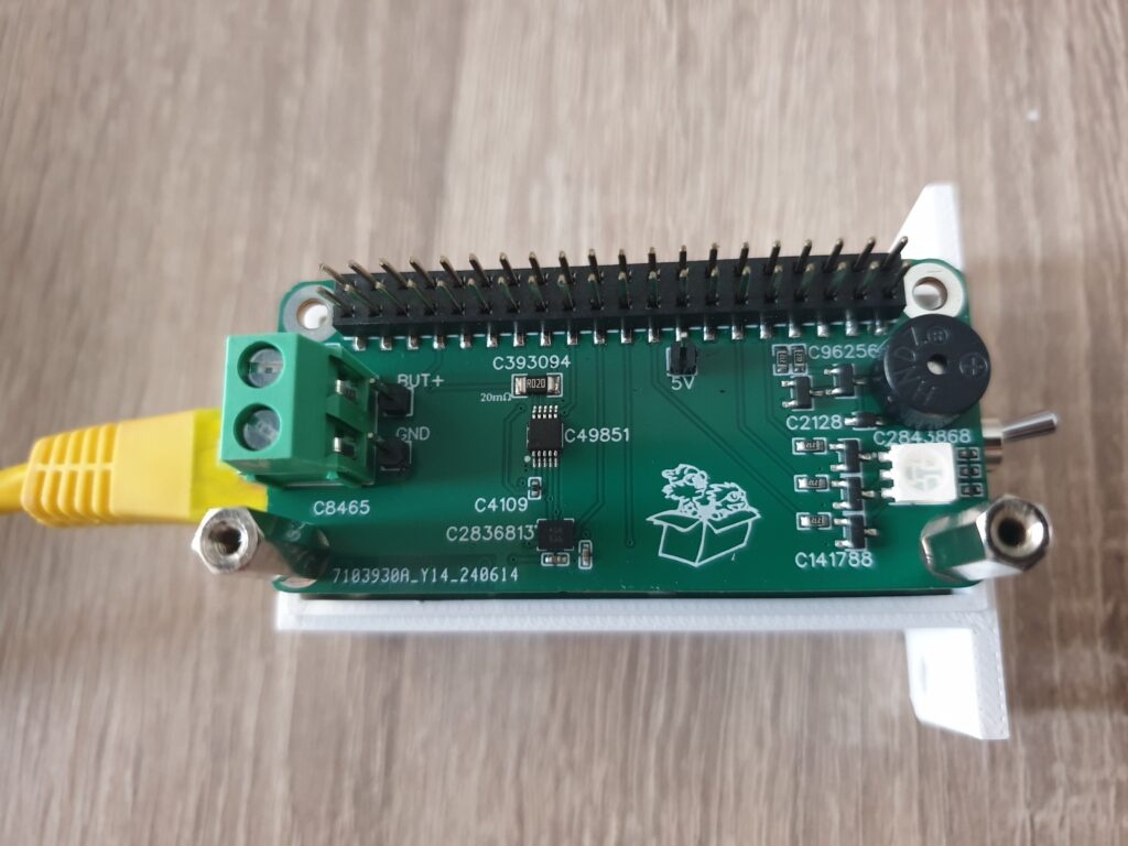
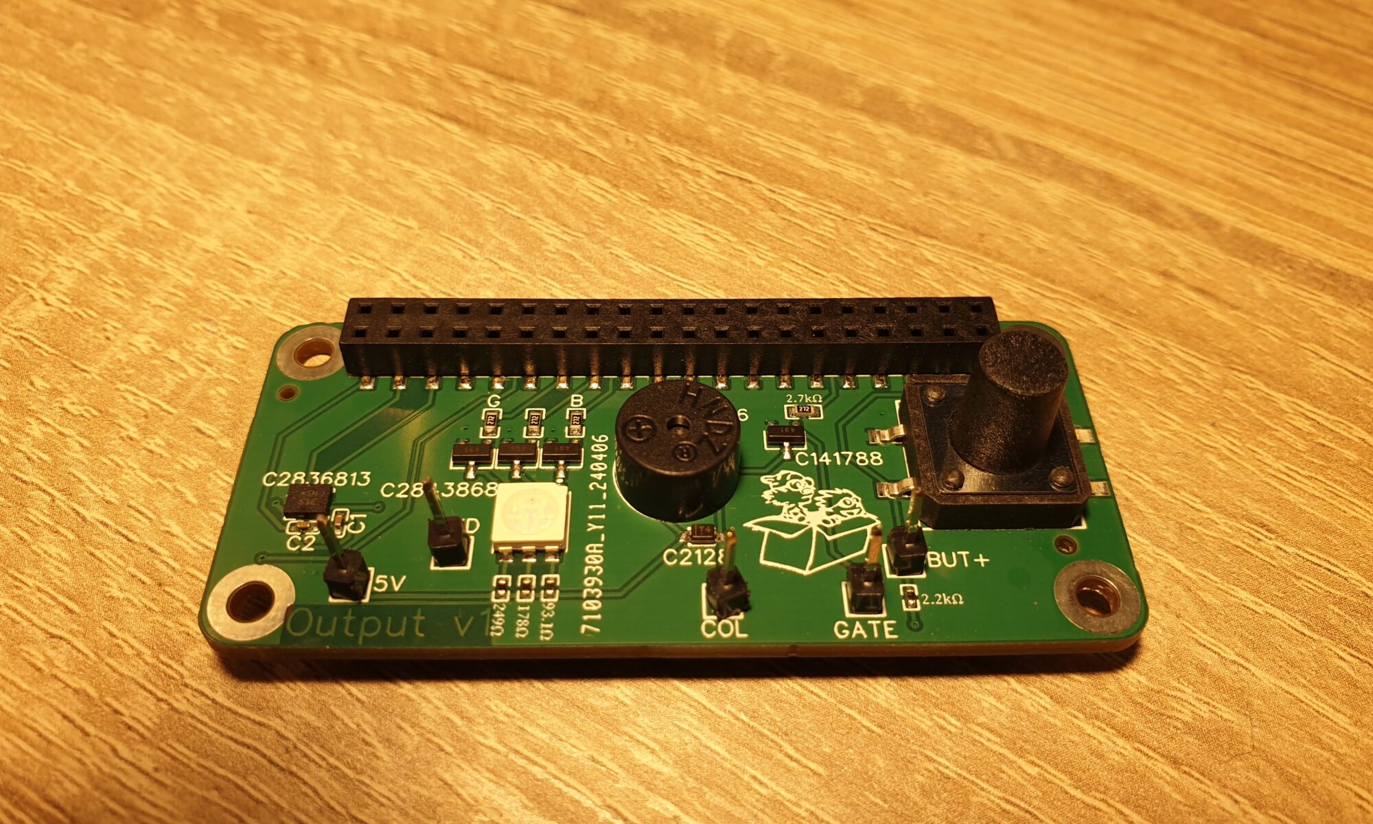
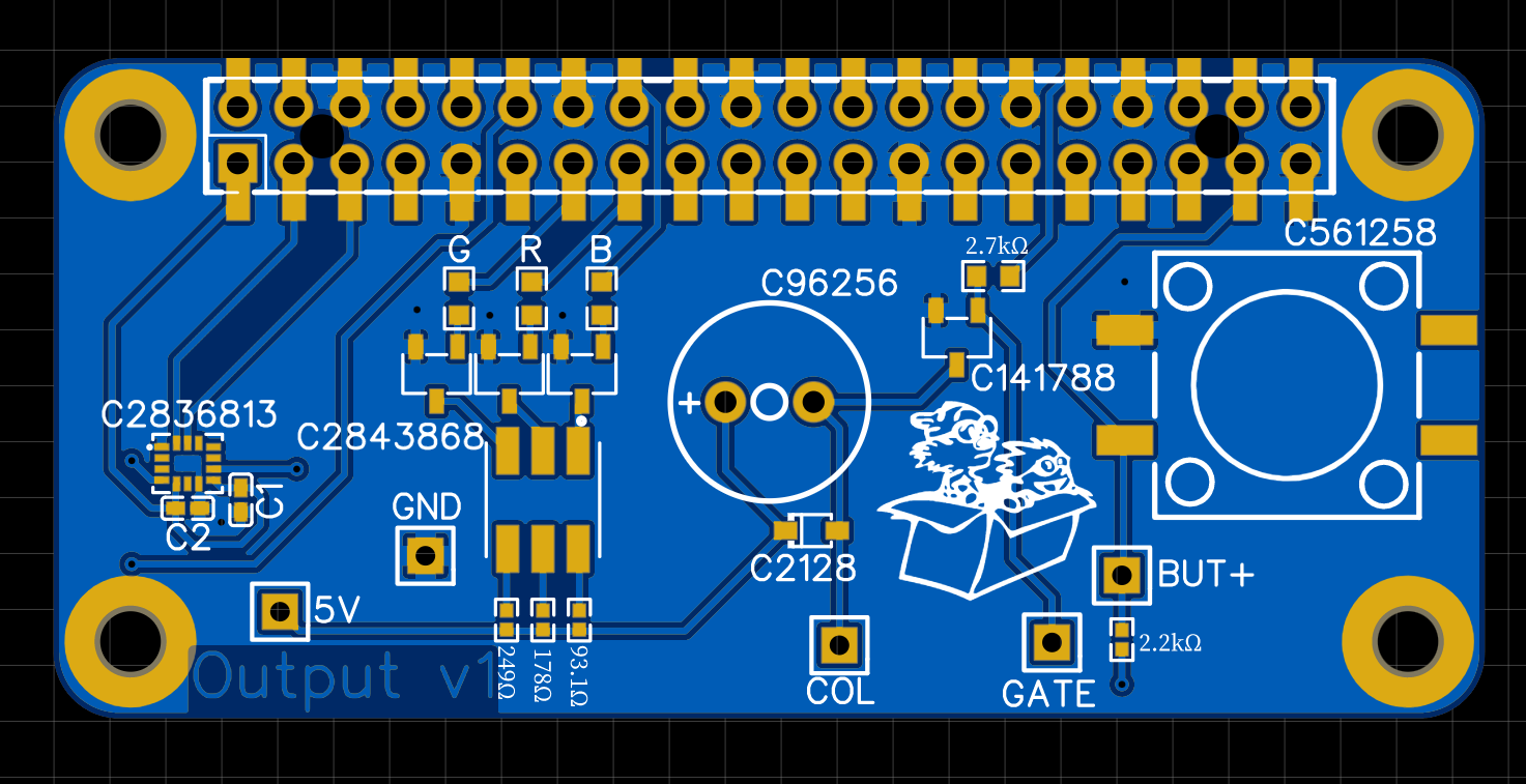
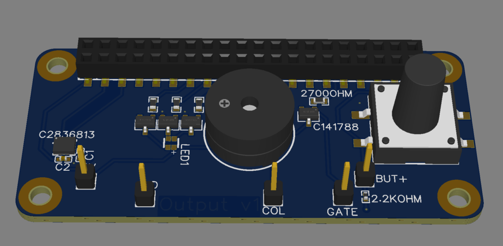
Last time – already a month ago – I wrote about uncertainty rearing it’s head, a new output PCBA and the PushButton of my project. Today, about three weeks before I drive to the Sommertreffen with my project, I have almost finished production of a series 5 devices…well almost.

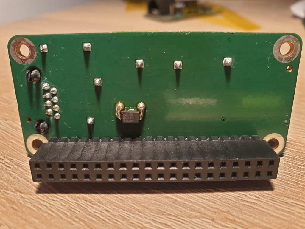
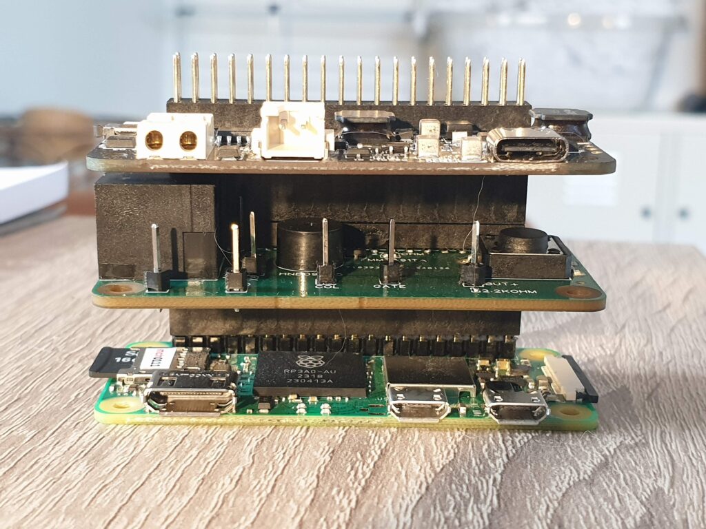
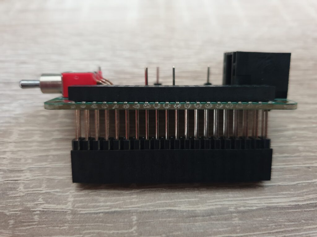
I ordered just one piece too little of an important piece: the extra-long Pi extension headers I use to stack all PCBAs. It’s a bit of a bummer, but something that I will resolve in the next few days.

Software bugs

The stacking mechanism used. The long header pins penetrate the PCB and the small female header.

The past few weeks I’ve been testing the device almost on a daily basis. This has shown some annoying bugs, which I’ve been able to solve.

My software consist of four programs that communicate with each other. Each program has a distinct function. Most of these programs can fail and be restarted very quickly. So quickly that the pilot does not notice anything.

The idea behind this is that bugs can always happen, but that individual parts of the software can fail without the system as a whole failing. For example, if LXNAV sends me malformed input, the process responsible for decoding it will just crash and restart.

That’s all very nice and works great in practice… as long as the code responsible for restarting a failed program works. Off course, this is where I found a bug. Things were not restarting. Even worse, the software responsible for restarting a failed program would lock up itself. This is fixed now.
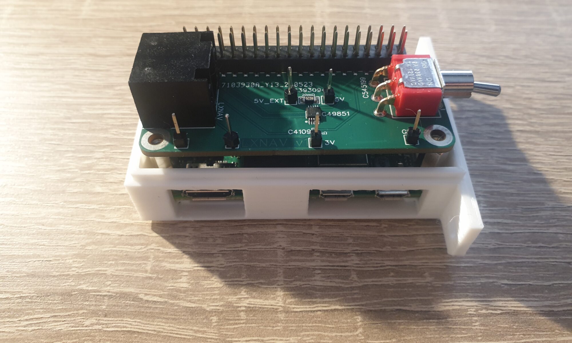
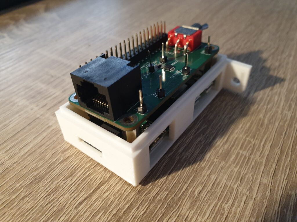
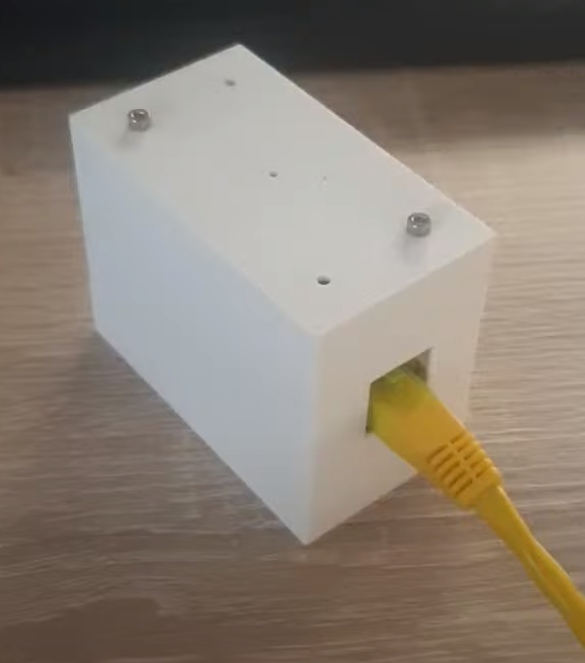
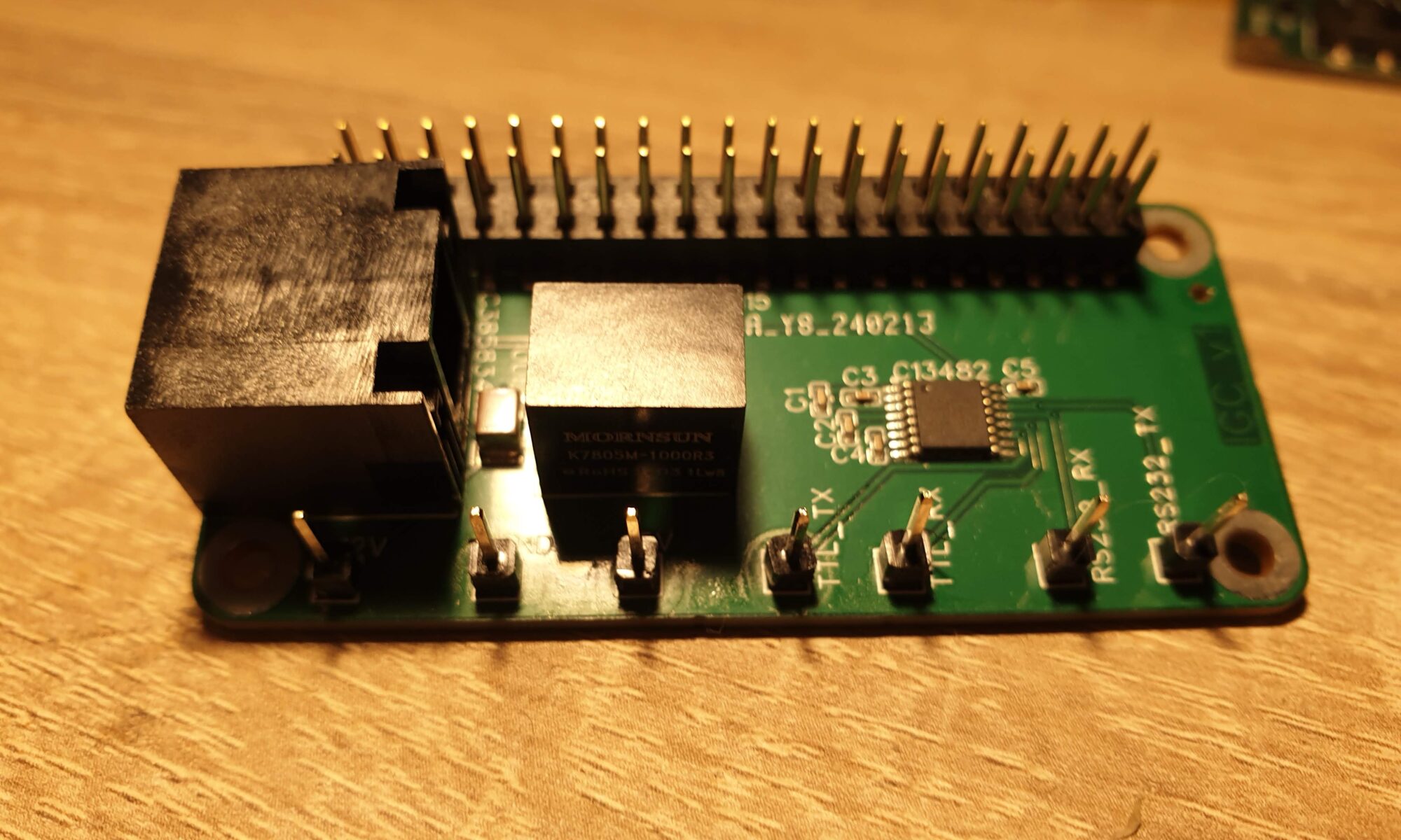
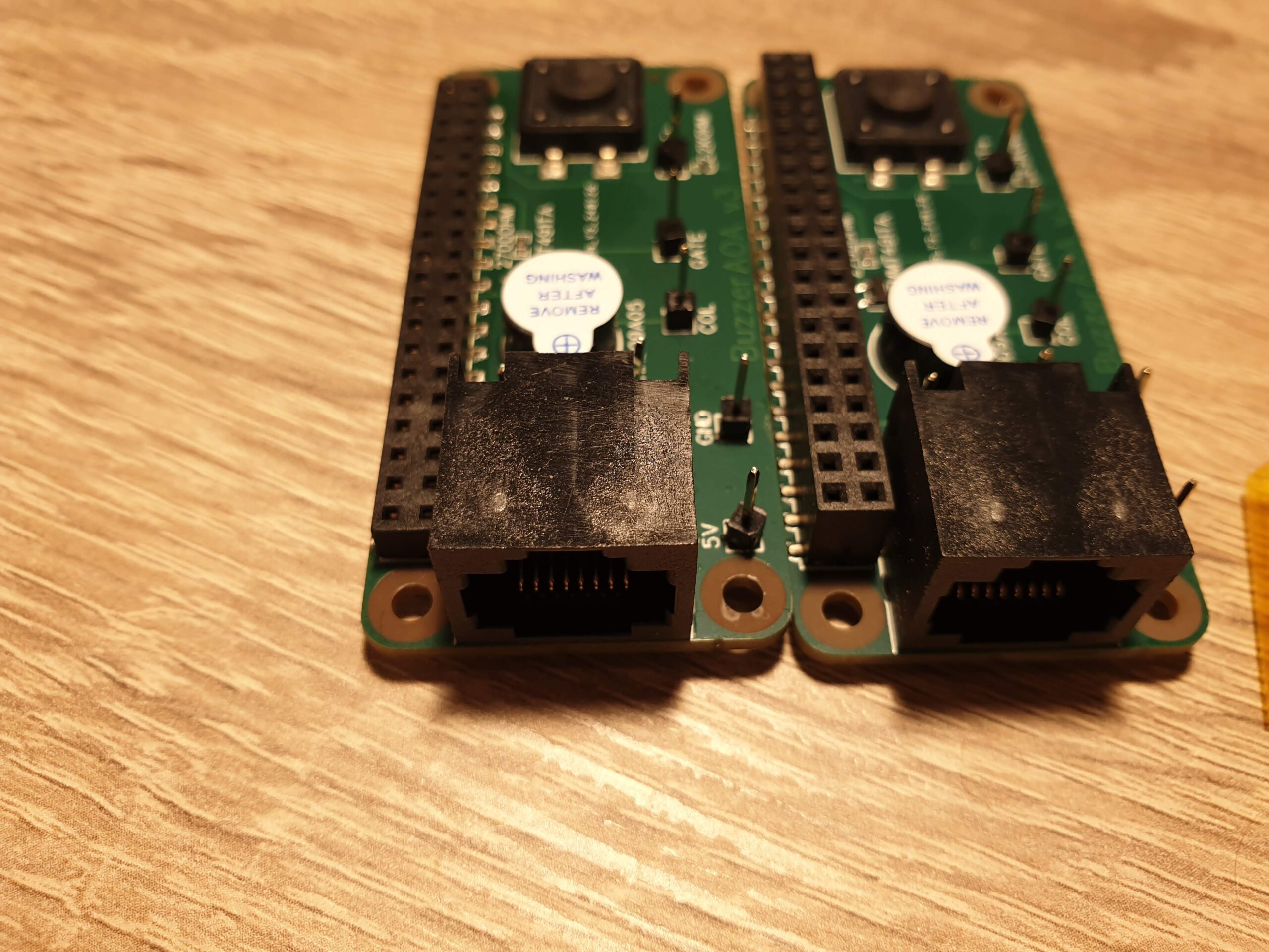
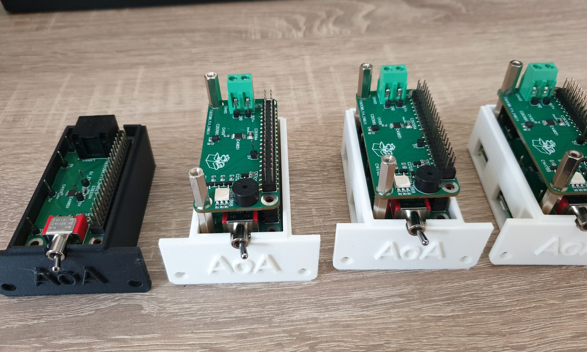
Series production

Four Raspberry Pi Zero 2W’s waiting for additional PCBAs to be stacked on top. The black enclosure will be used in the Zacher Simulator, to make pilots familiar with the device. The fifth device is running tests.

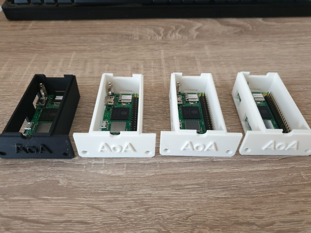
After my holiday, I started to prepare for a series of 5 units. Because I had already built one unit, this was rather easy: just order 4 more times everything that I had already used.

Today the last parts arrived and it took me about 45 minutes to assemble everything. I believe that this is where eXtreme Manufacturing and especially building fully functional prototypes shines. Because I’ve been involved with 3D printers, hardware suppliers and everything else… I know what works and what doesn’t. Not only have I assembled the device many times before, I also have a gut-feeling about the manufacturing consistency of each supplier and their delivery times.

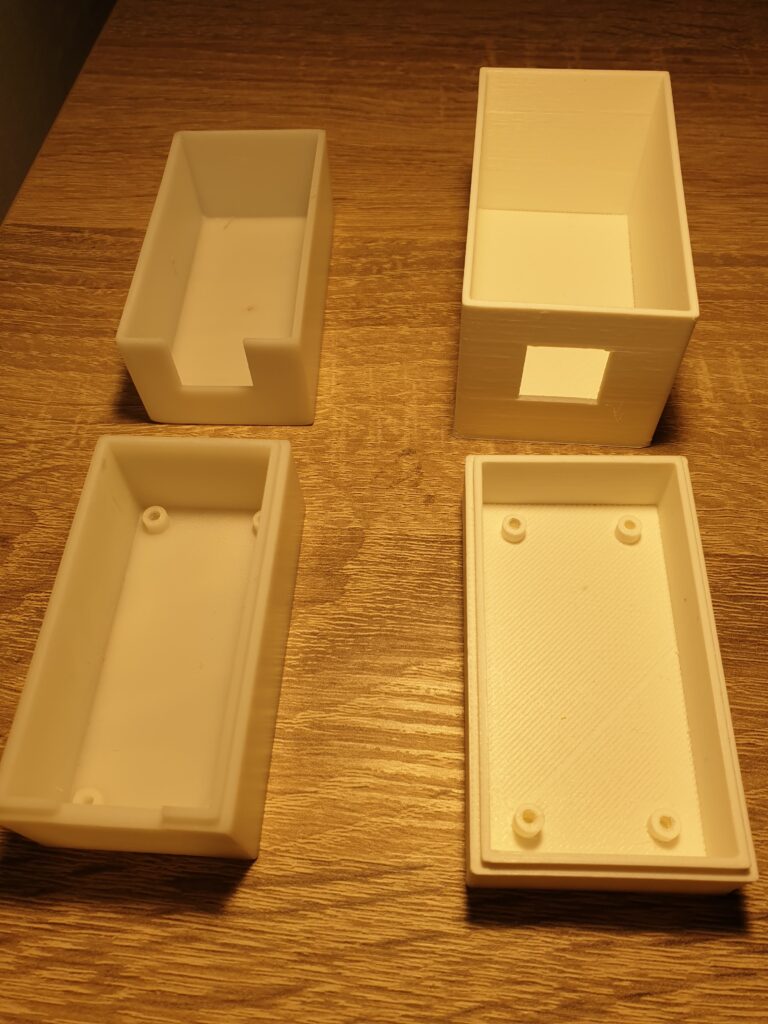
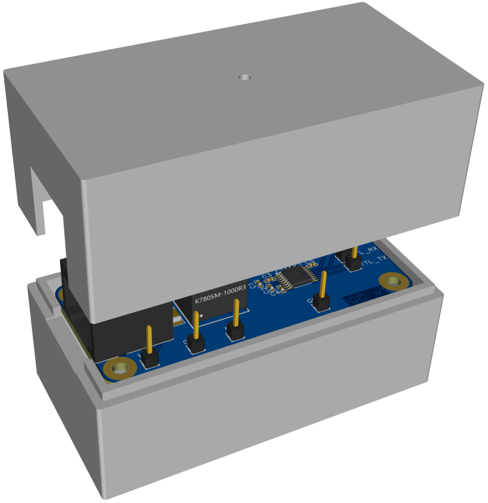
Where the device has stable interface between parts, I had the choice of using previous iterations of a part if I wanted to save money. In the previous iteration the 3D printing supplier gave me some extra parts that they considered to be bad quality (the color was not perfect), and I was able to re-use those parts.
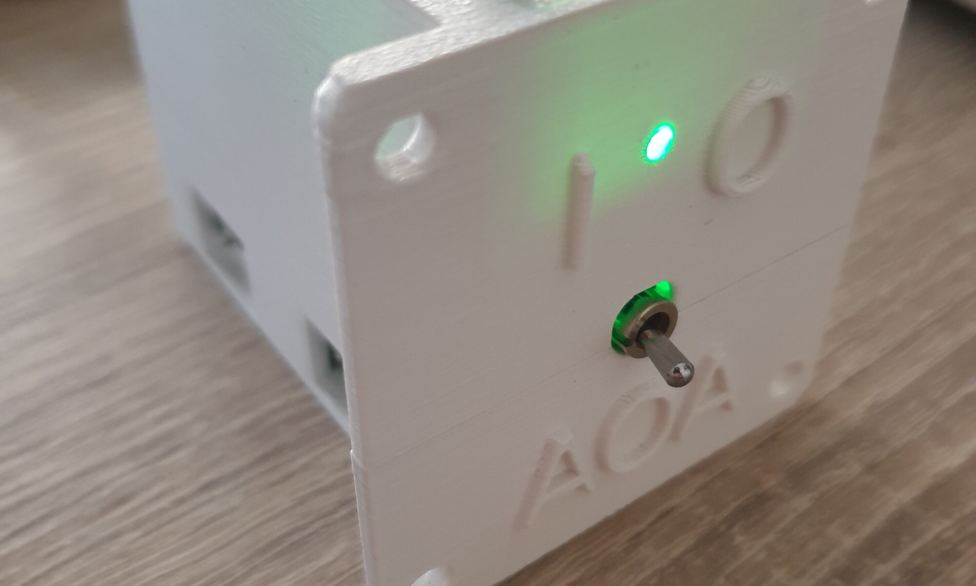
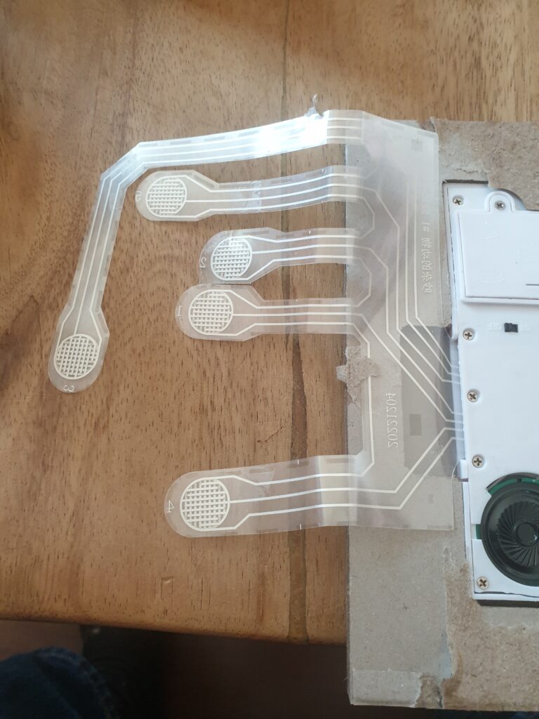
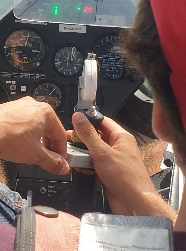
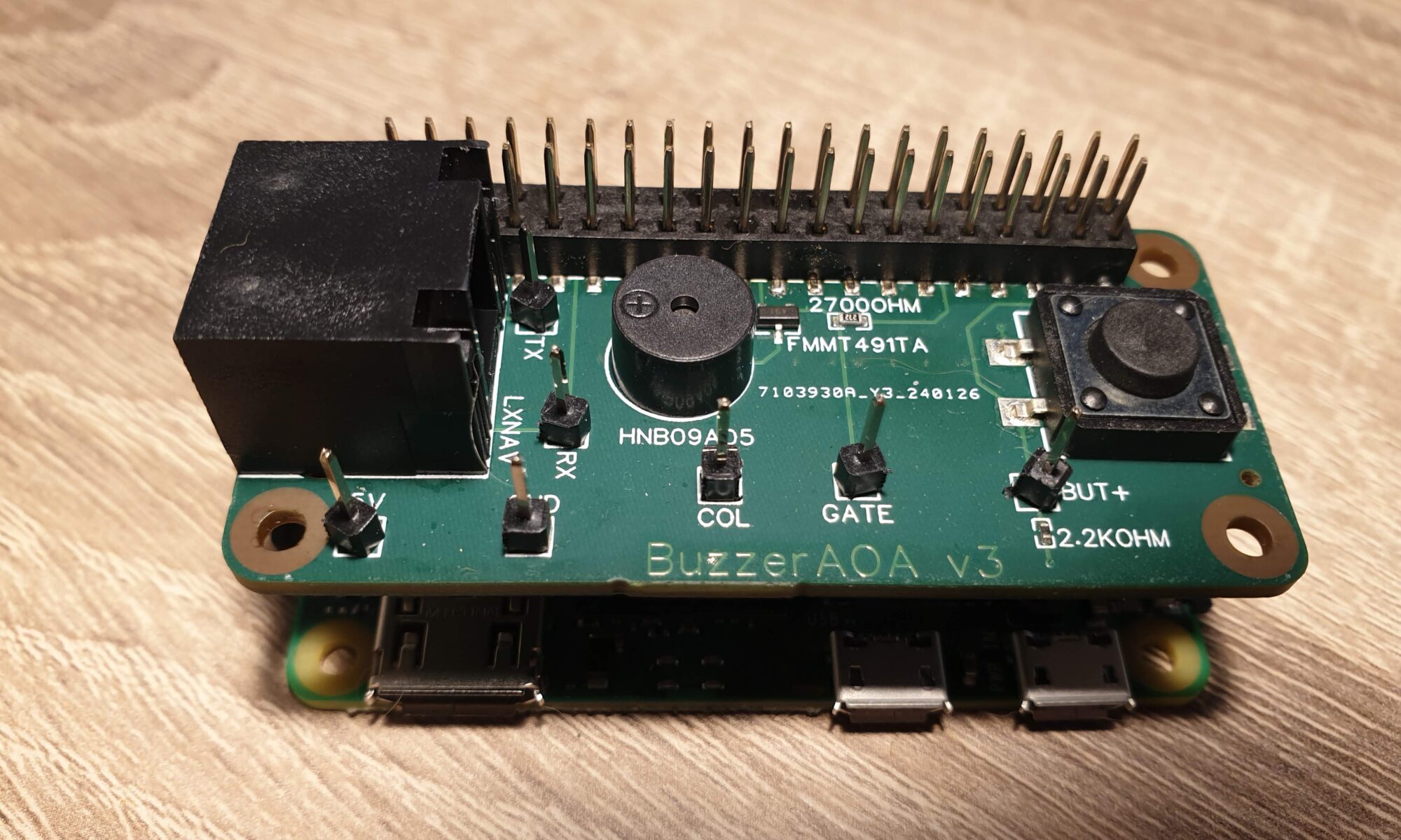
PushButton

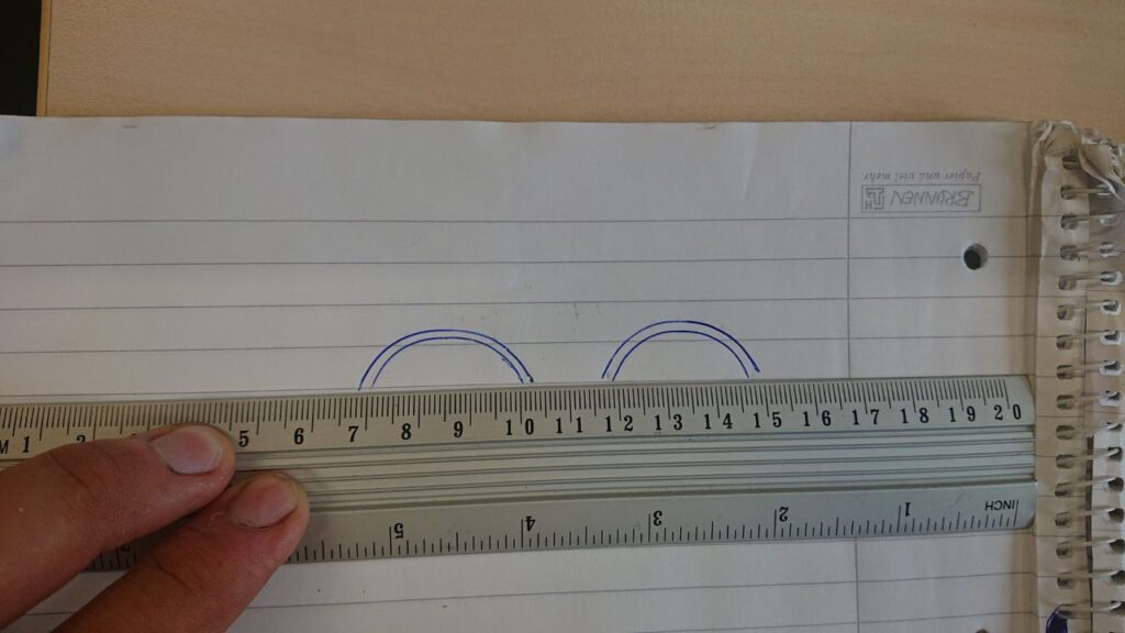
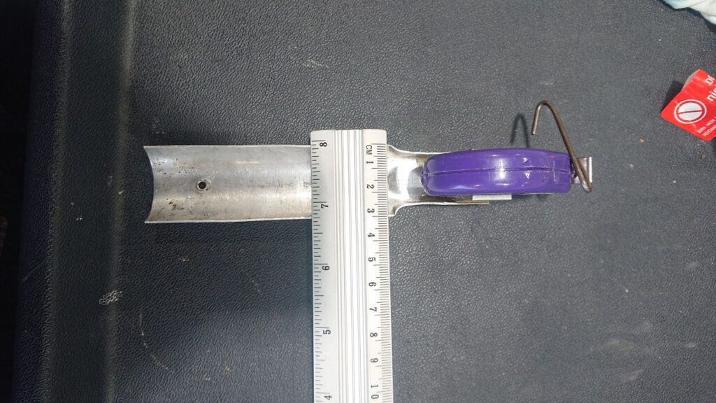
A month ago I was still struggling a little bit with the PushButton and mounting it on the stick. In an effort to get more grip on this situation, I asked DLR for some information on the metal bracket that is used to mount the measuring tape to the flight stick.

The measuring tape and metal bracket that mounts it on the flight stick.

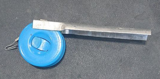
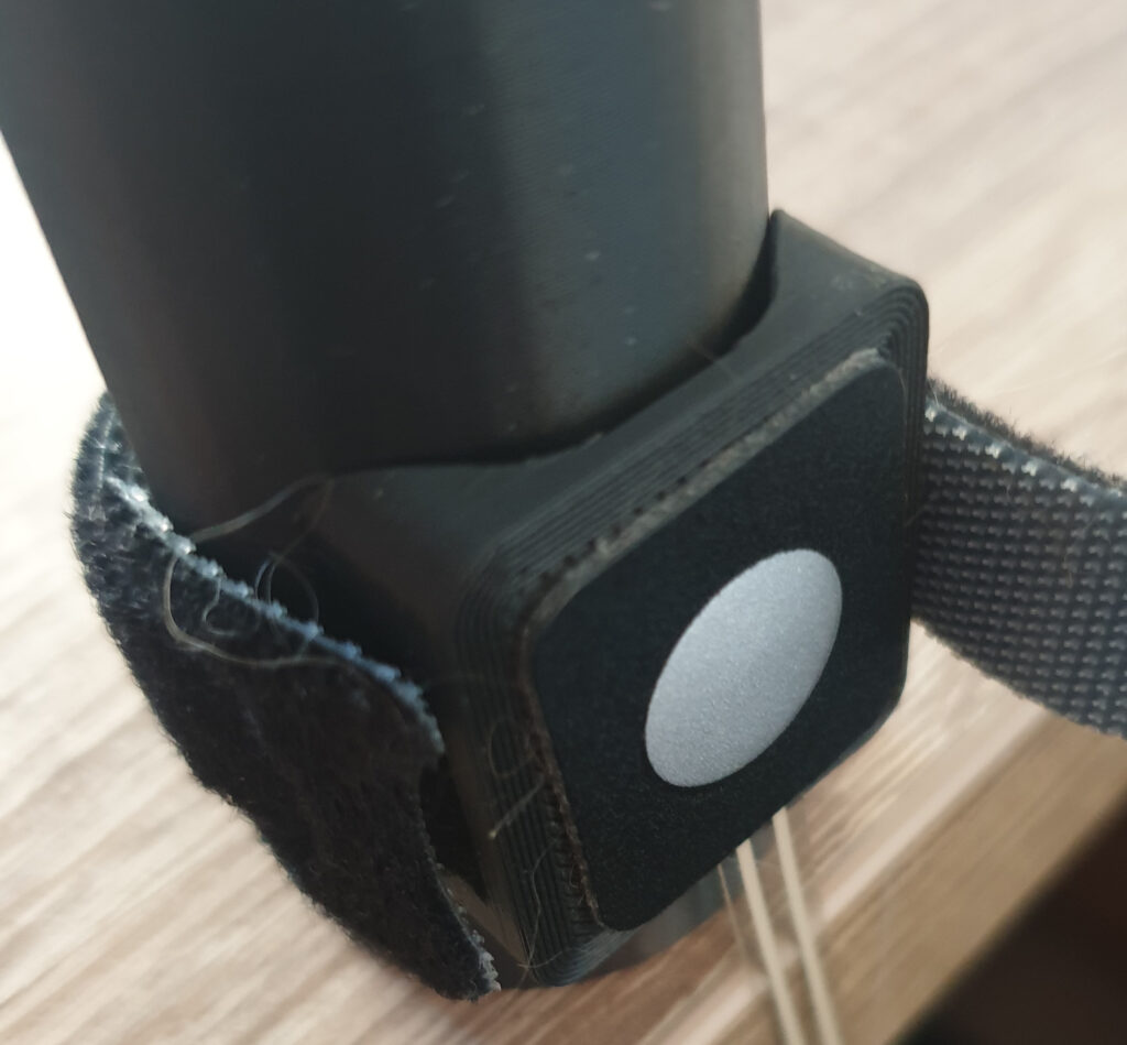
DLR was able to give me accurate measurements and a profile of the metal bracket. Roald, who you might remember from his insights in the PushButton from previous posts, was able to make a 3D model of a flight stick with the metal bracket mounted. He also created a small adapter that allows me to mount the PushButton on a flat surface to the flight stick. Not only did he provide me with this model, he also donated the velcro straps to secure the entire thing!

A mock of the flight stick with bracket and the adapter with the PushButton.

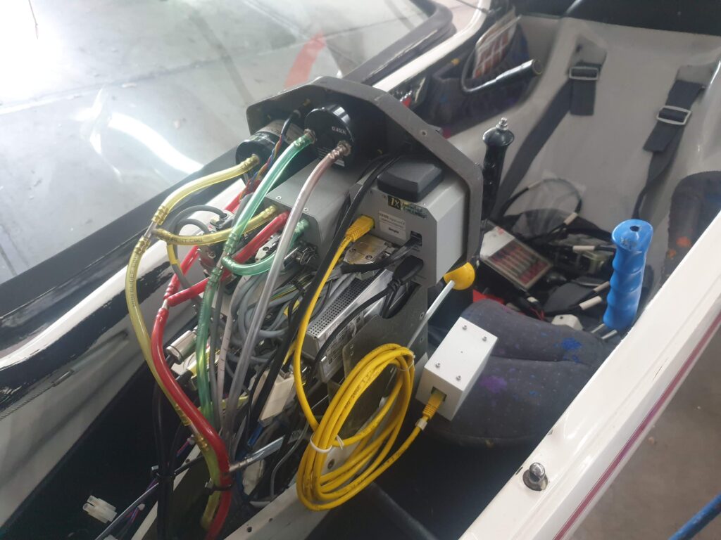
Testing final assembly

The wiring between the main unit and the PushButton. Twisted pair, DuPont cables, flex-PCB.

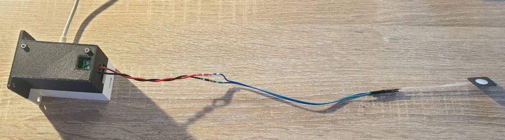
Despite my efforts, final assembly will still be a bit hard. The majority of the cable will be a twisted pair. The PushButton comes with a female DuPont connector. So I have two options: buy DuPont crimping tools or abuse existing DuPont cables as adapters. I’ve decided to do the latter. This means that I will connect one side of the DuPont cable to the twisted pair cable. I will do so using solder sleeves. While this does work, it’s not pretty and still requires tools: a heatgun.

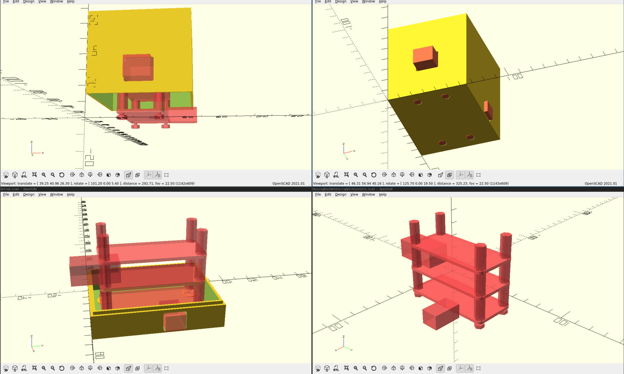
Some closing thoughts about XM

With the Sommertreffen now approaching, I find myself starting to draw preliminary conclusions about the development and my first real-world experience of eXtreme Manufacturing (XM).

Perhaps the most prominent thought is: the importance of early feedback cannot be overstated. I was completely surprised by the feedback I received at Aero Friedrichshafen. And I cannot count the amount of times that I wished that I had a glider where I could just install and test things with. Early feedback is immensely valuable. I also understand why most Agile coaches say that Agile cannot be done in isolation; in order to receive early feedback you need partners that are willing to evaluate your early work. I’ve tried to evaluate my own work by using a simulator, but it’s just not the same.

Once you have that ability to regularly evaluate, other things like Modularity become very important. If I would have had a glider at my disposal, it would have been a big effort to swap out versions. Anything that takes more than a few minutes easily becomes a mental hurdle. The human mind will always tend to over-estimate it’s own ability to predict the future. So the bigger that hurdle, the more assumptions you are tempted to make and the more re-work you will have to do. Reality tends to be surprising in all kinds of unforeseen ways.

Once you have these things down, you can – in theory – replace things pretty quickly. I can release new software after every flight, but I don’t think I will. Despite my efforts for using Test Driven Design, I have not been able to drive this far enough to be confident about releasing new software to all 5 devices blindly. This is where I would like to improve. Ideally I would like to be able to enable auto-updating on without any worries about software quality.

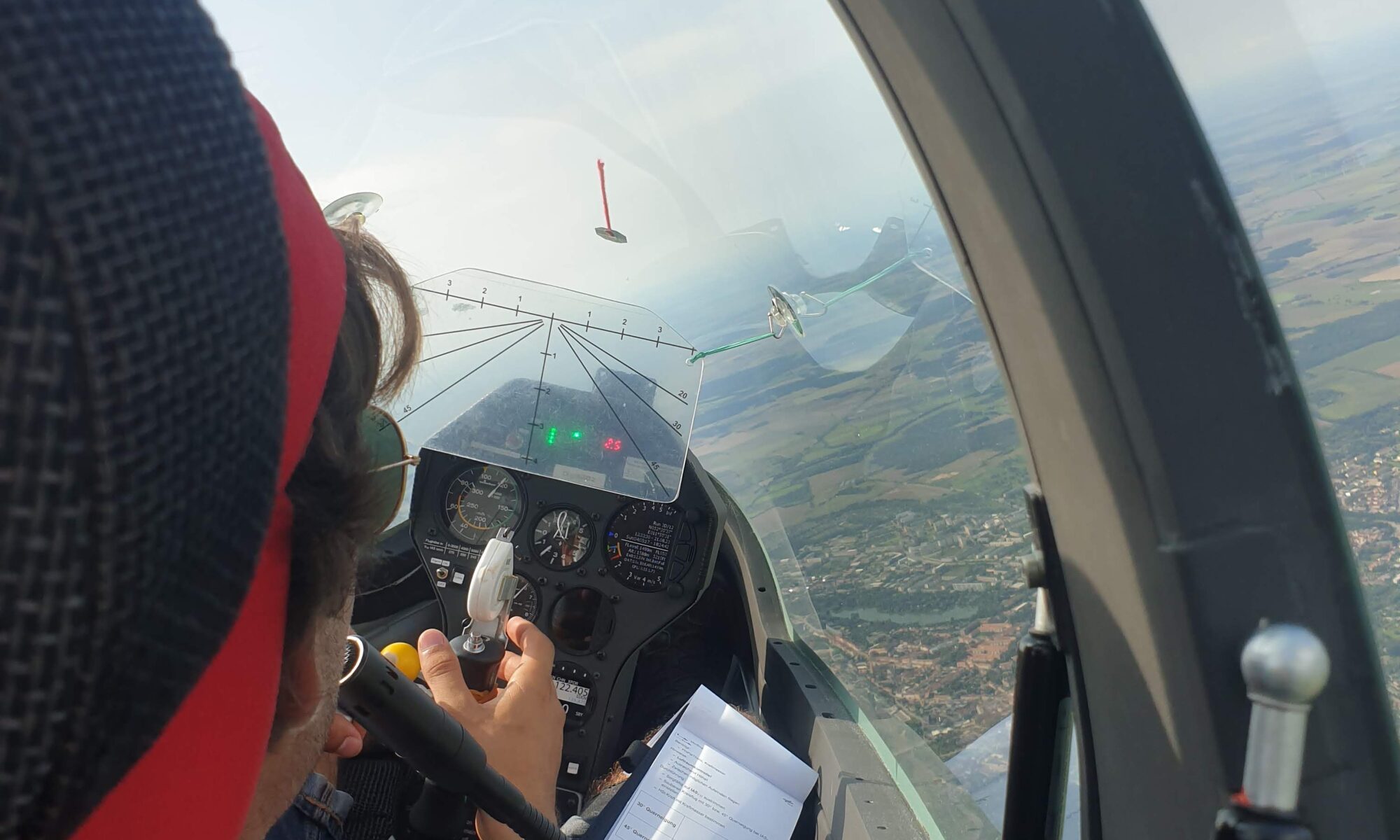
With my nerves settling down and my devices complete, I’m looking forward to test this thing out in Stendal. I am intensely curious what will work as intended, what unexpected issues will arise and how my device will be regarded by the pilots. I intend to update the device several times during my visit, in order to improve it and get as much feedback on it as possible.

Project Hobbes: Part 11 – Final glide

Last time, I wrote about my happy experiences with Test Driven CAD, registration at Idaflieg and some adventures with the PushButton. When I write this, I have only two months left to my visit at the Idaflieg Sommertreffen, which doesn’t feel like a lot…especially if you take into account holidays and work. The good news is, I’m on final glide towards having at least support for the LXNAV S80/S100 variometers working.

Nerves

The doubts that creep up in my mind are all rooted in one thing: the lack of real-life testing. I’m starting to be convinced that this is where this eXtreme Manufacturing (agile) stuff helps a lot: you test early and often. I wish I could have tested more, and sooner. I have successfully tested a lot of software with the usual techniques (Mocking, Faking). That’s not where my doubts are. They are more centered around the stuff I can’t easily test: the entire Linux system I’m dragging along, the manual, etc…

Enclosure updates

In the last version of the enclosure was a hole where the On/Off switch can go through. I just had trouble installing the contents into the enclosure. The fix was very easy: split the enclosure at the location of the switch instead of below it. I thought it would also be nice to have the positions of the switch be visible on the outside, so I added some text indications on the device, as well the text “AOA” to indicate what the device does.

This version of the enclosure is printed with ASA, which is supposedly more resistant to UV radiation and heat. The previous version was printed in PLA by Roald. For crash-worthiness, I verified that the enclosure can handle at least 6kg of weight. Since the device itself weighs almost exactly 100 grams, this is equivalent to 60G. Should be good enough.

Output PCBA

The latest version of the Output PCBA. On the left the screw terminals, IMU center-bottom, current-shunt center-top, LED and Buzzer on the far right.

I’ve revised my Output PCBA quite a bit. With the realization that the PushButton should really be removed, I’ve investigated the method of connecting the PushButton to the stick and to the read-end of my device. Since the PushButton used to be placed at the very front of my device – and the connector is now at the very rear – I have had to change the Output PCBA quite a bit. The PushButton will be connected using old-fashion screw-terminals. I’ve looked at many connectors, only to realize that this solution is by far the most flexible.

The RGB LED is now located at the very front of the device, which should it good visibility to the pilot. The RGB LED will be used to indicate system status to the pilot. When the device detects it might malfunction, the RGB LED will turn red to indicate that the device should be turned off with the On/Off switch.

In the last iteration of the Output PCBA, I switched from an Active Buzzer (which generates a fixed tone at 2700Hz) to a Passive Buzzer (which can generate many tones, but needs a PWM signal to do so). I tried to see if turning the Buzzer on and off using software timers worked well. It more or less does, but sometimes the jitter involved in software timing becomes noticable. Realizing that I have two PWM lines available in the Raspberry Pi Zero 2W, I decided to use both: one for turning the Passive Buzzer on and off, the other one to change the tone. This means that I only need to tell the PWM hardware what to do and it will continue to do so forever. This also should reduce CPU usage a bit, and therefore power consumption.

PushButton

A side view of the measuring tape mount.
A front view of the measuring tape and the mount. Tape rolls out towards the camera (instrument panel in flight).

My current plan is to mount a Membrane Button on the measuring tape mounting on the stick. I’m no too sure if the button can nicely follow the curvature of the plate, so I will make a replica and test that. There is a Plan B: handheld pushbuttons.

Idaflieg Sommertreffen

I received the happy news that my project has been accepted for this year’s Idaflieg Sommertreffen! This means that up to 4 aircraft will be fitted with a copy of my Angle of Attack indicator, and the pilots flying those aircraft will provide me with feedback on the device. I’m both very excited and grateful to be accepted, especially since I’m not a member of an Akaflieg and there’s some funding involved. In return I will write an article (both here and in Idaflieg’s winter report), and I’ll present the results of the project in the next Wintertreffen.

Part of the feedback I received was to investigate if my setup falls within the standard changes as defined by CS-STAN. It appears to fall within the description of CS-SC062a: Installation of an awareness function or awareness device. This means I’ll spend some time to look at the recommendations and requirements outlined in this standard change, to make sure my device complies and perhaps revise the manual a bit.

Speaking of a manual… last time there was none. I have started to write one, also in an effort to detect any blind spots. I’ve also started to ask some Akafliegs if I can mount my device in their gliders.

Testing

Since I’ve not yet had my device connected to an LXNAV S80, I’ve asked a friend from my gliding club if I can lend his Glasflugel Libelle with S80 for some testing on the ground. The Libelle is awesome in the sense that you can easily remove the instrument panel from the glider. So I spent some time with my friend’s panel…and everything worked right out of the box! That’s a huge confidence boost!

With the Sommertreffen approaching and approval to execute my project, I’m excited to get everything done. Most things are in place and work consistently. Some things, like the PushButton and the Manual need some attention. I intend to start series production a month in advance, so there’s probably one iteration left. We’re on final glide.

Project Hobbes: Part 10 – Mechanics

Last time, I wrote about some ground tests I did and the preparations I made for a refactor. In the past two weeks I’ve been able to refactor the project’s enclosure quite a bit, thanks to my preparations in OpenSCAD and my friend Roald, who owns a 3D printer..

First Enclosure

At Aero Friedrichshafen I learnt that the device should really be mounted in the instrument panel, in either a standard 57mm hole or in a standard 80mm hole using an adapter. So, as part of the “Test Driven CAD” efforts I made, I modelled the adapter-plate with screws and made a test make sure my neither the PCBAs nor the enclosure interfere with it.

I was very keen to prove to myself that this “Test Driven” bussiness has the potential for me to get things right the first time. TDD has been a massive improvement in my productivity as a software developer, so I was hoping to get similar improvements in working with CAD. I wasn’t disappointed…

First I added “ears” to the enclosure, such that it can be mounted in a standard 57mm hole. After I spent countless times inserting and removing the Raspberry Pi Zero 2W from the bottom of the enclosure, I decided to add some holes for the ports I use: micro-USB for power, USB-OTG for keyboard/mouse and HDMI for display. I also added a hole in the enclosure through which I can (for now) press the PushButton that’s on the Output PCBA.

Full of confidence I sent Roald a bunch of STL files…and he told me things were not okay. The top and bottom showed overlap and could not be mounted together, and my PCB support pillars on the bottom of the enclosure were too thin to actually print.

I implemented a test to verify that top and bottom do not overlap, and made some changes to get it right. For the PCBA support pillars, my CAD drawings were telling me that there is a conflict between the Raspberry Pi’s pin header and the support pillars (more specifically: the counterbores in the support pillars). I realized that I really don’t need counterbores near the Pi’s pin header, since the stack of PCBAs provides more than enough rigidity due to the pin header stack itself. So I removed the entire set of standoff screws on one side of my PCBA stack and solved the issues with the PCBA support pillars entirely.

I pushed my code to the CI/CD server and collected a set of checked STL files, forwarded it to Roald and waited. The next day at the airfield I received a new version of my enclosure… talk about quick feedback!

The first version of a CAD-designed enclosure that works! HDMI needs some work, but that’s it.

I was very pleasantly surprised by this enclosure. Everything fit inside as planned, I could close the enclosure and mount it to the adapter-plate. Apart from a small miscalculation for the HDMI port, everything worked exactly as intended. Test Driven CAD was a success! I quickly grabbed my laptop and fixed the HDMI issue. To the next version!

Registration at Idaflieg

Around this time it was time to officially submit my project to Idaflieg, so it can be considered for this year’s Sommertreffen in August. I was asked to describe my project, it’s goals, what I’ll do with the results…and potential safety risks. Using some of the experience I’ve recently gained on this topic from my workplace, I saw some potential risks that could drastically increase pilot workload. Not good. It was very clear to see that one solution would answer them all without a doubt: a hardware On/Off switch. Up to now I had always wanted to do everything in software, but it is beginning to dawn on my that you have to account for buggy software.

I finished the Idaflieg form and submitted it, and immediately started to redesign my Input PCBA to contain a hardware On/Off switch. Since the switch should penetrate the enclosure at the front, this also means changing the enclosure (adding a hole at the right place). I found out that my PCBA was too far away from the front of the enclosure to make the switch actually usable by the pilot. So it was time to really test my CAD skills now and reduce margins around the PCBA stack to 0.5mm and make an additional hole for the SD-card to stick out. This was all done in CAD, and I kindly asked Roald to print a new version of the enclosure again.

The second enclosure. The SD-card fits, and HDMI port is now aligned. The new On/Off switch is also visible.

Both the new PCBA and the enclosure arrived at the same day. I put in the Raspberry Pi, and saw that everything fit perfectly. This was a really proud moment! The hole for the On/Off switch was exactly at the right place and the SD-card also aligned perfectly. The only issue was…the switch now prevents me from sliding the entire PCBA stack inside the enclosure. Not totally unexpected, but something that must be fixed in the next iteration.

The PushButton

I was really struggling with the wish of having the PushButton mounted on the stick. Since there is no standard shape or even diameter for sticks in gliders, I found it difficult to come up with something that will work reliably with very little effort or customization. So I started to ask around.

Not only does Roald own a 3D printer, he also possesses the kind of hands-on creativity that I often envy. Things just come to him in a way that I can’t replicate. When I met Roald at the airfield, he showed me this:

Roald shows me his son’s book with music

These booklets are just a few euros, and contain about five of these membrane pushbuttons with flexible PCBs attached to them. I got one of them, and opened it up:

The insides of a different music book.

It contains membrane buttons. They can easily be mounted to anything with a bit of tape or even some Velcro. After a bit of googling I found that there also exists a similar technology called metal dome buttons, and ordered of of those:

Test of a metal dome button. Note the tactile feedback it provides.

I think this might work well, since it can be mounted on the already-present Zacher tape measure mount. It provides tactile feedback as requested, and can easily be installed or removed. The flexible PCB attached to it appears to be strong enough, although the DuPont connection at the end still requires some thoughts.

I am extremely pleased with the amount of progress that I have been able to make in just two weeks. This was accompanied by a feeling of playfulness and flow, which seems a good indicator of being on the right track with eXtreme Manufacturing. Next up is getting the PushButton right, and perhaps starting to write the pilot’s manual.

Project Hobbes: Part 9 – Foundation

Last time I wrote about how I got valuable feedback during my visit at Aero Friedrichshafen. As I mentioned, I’m now forced to go back to the drawing board with my enclosure. But not before I gather some more feedback…

Ground tests

Ground tests in one of my club’s DG-1000S gliders.

Unfortunately I was unable to test my hardware in flight, but I was able to spend an entire day with the device connected to one of my club’s DG-1000’s. These are all equipped with an LX8000 and they have the PDA port avaiable for me to connect to. My main objective was finding bugs and more importantly: checking EMC compatibility. I connected everything and found no sings of any EMC issues. During the five hours everything was connected, the radio didn’t turn on, other instruments didn’t behave in an unusual way. No extra noise was audible over the speakers. I consider EMC to be okay for the LXNAV version of my hardware. The other input board, which features a DC-DC Converter (12V to 5V) module, will need a separate test.

I found a few bugs here and there, which were (ironically) all located in parts of the code that I hadn’t covered with Test Driven Development. I can do a better job at separating code that steers hardware from code that’s purely logic. That way I can test more of my code and find these bugs earlier.

After some bugfixes, I could see data flow. The $LXWP0 NMEA sentences from the LX8000 were parsed and the Indicated Airspeed was extracted from it.

My “Tap Detection” algorithm is too sensitive and will be removed. For the final Idaflieg tests I need a physical button anyway, so no use in keeping it around.

Test Driven CAD

A new enclosure arrived during the past few weeks. This enclosure was fundamentally different from previous versions in that I designed it entirely in OpenSCAD. Like with all first tries, this first enclosure was unusable. However, it did reveal important lessons about my CAD process: there are way much details in a CAD model for me to keep track of.

So I started to wonder what “Test Driven Development” in CAD might look like. I want to have an automatic check that tells me if my design satisfies certain constraints. Perhaps the most important constraint is: do the contents of the box actually fit? Another one might be: can I plug in the RJ45 cable? You get the idea…

I solved this by modelling the contents of the enclosure, the PCBs, the standoffs, the nuts and bolts. I then created a scene that is defined as the intersection between the enclosure and the contents. If there is any conflict between the enclosure and it’s intended contents, this intersection will not be empty. When I render this intersection from 3 angles, all 3 images should be empty. To check if the images are actually empty, I wrote a small python script.

I can now make changes in CAD and get feedback on my changes in a matter of seconds. This makes me much more confident that my next iteration of the enclosure will work. It makes me also a lot more confident to refactor the enclosure.

PushButton

A closeup of the control stick of a DG-1001S, with measuring tape and force meter attached to the control stick.

One thing that I’m really struggling with is the PushButton location. I would like to place this at the stick, as one of Idaflieg’s pilots suggested, but it is proving to be difficult. There’s off course also a risk in mounting things to the stick, especially since there’s also a measuring tape mounted to the flight stick during the Zacher flights.

I have planned a session with a friend to try to address this, but anyone who has ideas is more than welcome to suggest them!

With some foundational work done, I’m starting to feel ready for a major refactor of the housing and the pushbutton. I am filling in the forms to officially submit my project for this year’s Idaflieg Sommertreffen, and I’m looking forward to the feedback from Idaflieg’s pilots.

Project Hobbes: Part 8 – Feedback

Last time I wrote about iteration 1 of the Output board, which more or less failed. I managed to burn the Red component of the new RGB LED and the new passive buzzer didn’t make any sound. I also introduced the BMI270 IMU, which could serve two functions: as accelerometer for planes equipped with an LX8000/LX9000 computer and a replacement for the pushbutton. I fixed this PCBA and visited Aero Friedrichshafen, where I got very interesting feedback from my friends at Idaflieg.

Fixing my mistakes

Both LED and Passive Buzzer now work.

First, I fixed my mistakes in the PCBA. With the help of a kind colleague, I learnt about the voltage drop across LEDs. The RGB LED now works fine and all components shine equally as bright. Indoors it is visible through the PLA housing, but it might not work in bright sunlight. We’ll see.

The buzzer now works too. I am working on some software errors, but the hardware works. In software, I’m using the timerfd mechanism combined with epoll to turn PWM on and off. Updating the timer does not appear to work, so I’ll probably write a small test program to see what I’m missing. While I use Test Driven Development for most of my code, I find it difficult to test code like this with side-effects.

The enclosure now also works, and I took that opportunity to bring my creation to Aero Friedrichshafen in order to show it and get feedback.

Feedback

The enclosure with PCBAs as I brought it to Aero Friedrichshafen

So I took my new creation to the Aero. I met up with some friends from Idaflieg to proudly show the progress on my project and received some feedback.

The first and most important feedback was: during the flight the pilot should be assumed to be with both hands on the stick. This means I cannot ask them to use a PCB-mounted button or the IMU to mark when the airplane stalls. There should be a button on the stick. I can connect this with long wires and screw-terminals to the PCBA, but this creates new problems. Since I’m now connecting something to a primary flight control, I have to ensure that I do not ever prevent the pilot from using that control. The wires involved cannot restrict movement, and they may not move everywhere during inverted flight. I have to think of a way to connect the button to the stick in a way that does not obstruct the measuring tape that Idaflieg pilots also use during the same flight. This will take some thoughts.

The second piece of feedback was that the box may not be taped to the top of the instrument panel. This was my initial plan, but the pilots clearly stated that this obstructs the view of the pilot and is not safe for inverted flight. Instead, I have to prepare my enclosure for mounting in a standard 57mm hole in the instrument panel. With an adapter I can also mount it in 80mm holes if that works better. This means the enclosure should be larger and should contain either horizontally oriented holes or something that screws can tap into. The experiments with self-tapping are not enough here, I need to have a very secure connection to the instrument panel.

Next steps

Especially for the enclosure it’s back to the drawing board! I decided to abandon creating my enclosures with EasyEDA Pro and started experimenting with OpenSCAD. OpenSCAD is a code-based CAD tool. This requires much more time to create something than for example Fusion360, but it gives me the advantage of including checks with the assert function. This allows me to check that the housing can actually interface with the PCBA stack, something which I had to measure by hand before.

I will have to change the Output PCBA in order to include screw terminals for the – now remote – pushbutton. If the instrument is mounted in the instrument panel, the RGB LED and the buzzer possibly also need to change place. This might involve a large change in some PCBAs, especially if I decide to change the orientation of the PCBA stack.

Before I redesign everything, I want to test one other important aspect: EMC. Since I have something that technically works, I want to fly with the system in order to get more feedback.

With the season well underway, the rain becoming more and more rare, and mountains of inspiration from Aero Friedrichshafen, I’m eager to test my project further and learn more. Let’s get this thing in the air!

Project Hobbes: Part 7 – Failure

Last time I wrote about the next iteration of the Output PCBA. The PCBA features the first I2C IC, the Bosch BMI270. A passive Buzzer instead of an active one, which should allow me to produce different tones if users request that. And finally an RGB LED, which should give me the opportunity to convey errors to the user.

Long story short: this PCBA was kind of a failure. The RGB LED was fried on first try, and the buzzer didn’t produce any sound. I also made some minor mistakes with the BMI270.

Reflection

This was the trigger for some reflection. When I started to design this PCBA, I caught myself thinking: “I am getting the hang of this. Let’s try to make bigger steps, and let’s make progress without asking for help. That’s too slow.”. I felt greedy, rushed.

These feelings are not new to me. Due to my inherent sense of urgency, this is a trap that I’ve stepped into quite a few times already when creating software. Where in more bureaucratic processes, I often have to wait on others, I find myself to be the bottleneck more often in Agile processes. This is not a bad thing, but something I have to learn to deal with. In making software, the thoughts involved are usually something like “This code is so simple that I don’t need to test it, let alone write tests in advance (as TDD prescribes).”. Which is inadvertently followed by the humble lesson that my code doesn’t work and that I’ve attempted to go too fast. I need to take a step back when I feel impatient and come back when I’m calm enough to follow the practices that I know work well.

The overall lesson, in both software and hardware, appears to be: slow down to speed up.

RGB LED

The RGB LED after some tests. The black burn mark is in the red component.

Back to what I screwed up and how I fixed it. The RGB LED had a datasheet…in Chinese. In my rush to complete something, I didn’t translate the datasheet and ended up mistaking the maximum reverse voltage (5 Volt) for the maximum forward voltage (around 2.4 Volt). The values for the maximum forward voltage differ per color, but the Red component has the lowest value. As a result that component burnt out immediately. Not knowing what happened, I tried to measure what was going on and had to conclude that everything worked as intended. Then I noticed the black marking on the LED itself. When I took unused PCBAs out of the box, I got what happened. I looked up the datasheet, translated it and got what happened.

Despite being able to fix this LED, I did conclude that the amount of light coming off the components was not enough for me. The intention is to illuminate the PLA housing from the inside, giving it a glow. This all has to happen in bright sunlight, so it needs to be bright. Power consumption is not my biggest worry here, since I will only turn on the LED in case of errors.

In an attempt to make all three LED components equally as bright (450mcd), I took some time to precisely calculate the needed resistor values for the PCBA. Not because the project requires it, but to show myself I understand this part of the design well.

Passive Buzzer

I expected the passive buzzer to work the first time, since I had already tested a passive buzzer on a breadboard. The setup was slightly different, as I didn’t use an NPN-transistor to toggle it, but I figured that my code worked and I had already used the same transistor for the active single-tone buzzer that I used in previous iterations.

Since my new buzzer was a passive version and thus does not include it’s own oscillator, I figured I wouldn’t need a flyback diode like I ended up needing for the active buzzer (remember the voltage spikes I wrote about earlier).

The buzzer only made small clicking sounds. Measuring what happened, told me that everything up to the NPN-transistor worked as expected, but the voltage levels around the buzzer made no sense and hardly correlated with the ON-OFF switching of the NPN-transistor. I was genuinely puzzled. My kind colleagues gave me some pointers on how they would connect he buzzer. In the end though, I ended up going back to the basics again: the datasheet. I found that I again had mistaken the maximum reverse voltage for the maximum forward voltage. I had picked a 30 Volt buzzer instead of a 5 Volt version.

So I replaced the 30 Volt buzzer with a 5 Volt version, and made sure that the datasheet also includes a application circuit. The circuit included a 1N4148 flyback diode I already used.

IMU – Bosch BMI270

I was genuinely excited about using the BMI270, since it is relatively expensive ($3 per PCBA) but has a good reputation among drone pilots. It is my first I2C device in this project, and thus a nice experiment to see if I understand the I2C bus on the Raspberry Pi enough to talk to it. According to online sources, no pull-up resistors are needed, so wiring was easy.

The BMI270 also has a downside: it is one of the few IMUs that needs to load firmware before actually working. Before loading this firmware, one can identify the device but not much more. The firmware is a whopping 8 KiloBytes large, which is kind of large compared to the 12 bytes that I normally read or write to I2C devices.

I was happy to see the device on the I2C bus immediately, and got to work with the “quick start” procedures in the datasheet. This worked more or less, except for the actual loading of the firmware. I got a very generic “Remote I/O error” from Linux, but a quick search online taught me that you have to send the firmware to the device in 32-byte chunks. That worked just fine, and after increasing some settle times beyond the datasheet values I was able to read accelerometer values.

One thing that I forgot with this device, is to attach the two interrupt lines that it features. These might save me some time and effort, since the device has a built-in step counter. The device might be able to interpret any “taps” as “steps” and thus give me an interrupt if a pilot taps on the device. Since I was already creating a new PCBA, I attached those two lines.

Enclosure

For the enclosure I ordered a third iteration. This was not intended to be production-ready, but instead to find the right diameter for the PCBA supports. In the first iteration, which was printed in SLA, I could have the m2.5 screw self-tap into the material. SLA appears to be somewhat elastic, which I suspect makes this possible.

The second iteration was printed in PLA, which appears to be less elastic. With the same diameter, self-tapping was not possible.

I went down a big rabbit-hole here to see what would be nice. My goal is to keep part-count as low as possible and make assemble simple too. Whenever I can use parts for multiple purposes at once, I would like to.

I decided not to use inserts that you have to melt into your 3d printed part, or tap threads into the 3d printed material. Instead I opted for mounting the PCBAs and securing the two halves of the enclosure with the same screws. This means the enclosure has counterbore holes on both sides, so I can use the m2.5 spacers I already have for both attaching the PCBAs and keeping the enclosure together.

This time I’m taking my time before ordering. I am getting closer to actual testing, so there is really no need to rush things. Slow down in the short term to speed up in the long term.

Towards an Audio Angle of Attack Indicator – Part 6: appearances

Last time I wrote about the things I did to close the feedback loop. I used an old PC with Condor Soaring to test the system, and I ordered an enclosure.

Results from Condor Soaring

My tests with Condor Soaring gave me a few interesting results:

  1. The system generally works as intended.
  2. One Indicated Airspeed update per second is worth testing, as long as I have 10 updates of the acceleration per second. This enables testing on LX8000/LX9000 devices, which my club has in their gliders.
  3. The system keeps on beeping after landing, and during take-off. This is very annoying, especially during the early phase of an aero-tow.
  4. The system lacks support for inverted stalls.
  5. My “let it crash” approach to software (inspired by Erlang) works and allows the system to recover gracefully from bugs. It does not restore the current maximum Angle of Attack, so I need to make that persistent.

Airspeed/Accelerometer

In order to allow me to work with LX8000/LX9000 devices, I need to have an accelerometer on board. After some pondering, I decided to make it an accelerometer/gyroscope combination in order to re-use this PCBA to create an IMU in the future. Due to the massive amount of smartphones that get built each year, there are loads of devices on the market. I decided to go with the Bosch BMI-270. I have good experiences with devices from TDK Invensense, such as the MPU-9150 and the newer ICM-20948. The latter however, works on just 1.8 Volts and wants to communicate with 1.8 Volt signals. This requires level shifters to and from 3.3 Volts. This means extra components and extra chances for making mistakes. I’m still learning about PCBA design off course.

So I decided to go the the BMI-270. It is more resilient against fluctuations on supply voltage than other alternatives and it appears to be quite stable. For what I’m currently doing it is probably overkill, but combined with the uBlox ZED F9P GPS modules I have lying around it might make a good IMU.

Beeping after landing

This problem was easily solved. When the derived angle of attack exceeds 1.25 times the maximum, the system becomes quiet. Using Test Driven Development, I wrote tests for this case, implemented the code and everything worked. Condor confirmed that it worked fine.

Inverted stall

The code was expanded to keep track of both a positive maximum Angle of Attack and a negative angle of attack. Depending on the acceleration that we sense, we compare the derived Angle of Attack against either the positive of the negative maximum. Again, using TDD I wrote the tests for this, implemented the code and tested it using Condor. It works fine.

Persistence

Whenever the system records the maximum Angle of Attack, be it positive or negative, it writes a file to disk with the values of both positive and negative maximum Angle of Attack. When the system starts it looks for that file and configures the values read from disk. Together with the restart mechanism I use, this makes bugs caused by transient phenomena a lot less annoying.

Enclosure

First (left) and second (right) iteration of the enclosure. Left is SLA, right PLA.

I ordered my first enclosure from JLC3DP. It was printed in SLA. I know this technique from a previous employer and I like how the results look. The surfaces a smooth. The first iteration cost me about $20 and took a week to arrive. I thought that this was a bit slow, so I turned to 3D Demand, a Dutch supplier or 3D printing. They were able to ship in 2-3 days for the same price (using PLA). This is not as smooth as SLA, but does the job for now. My first two enclosures both had errors in them, so having a quick feedback cycle is important for me. I want to get this right fast in order to start testing fast.

Hobbes

A friend suggested that the project really needs a name. We decided on Hobbes. I decided to adopt a logo for it too.

New Output PCBA

Since I have got something working, I’m looking towards simplification a little bit and towards the real-life tests in August. For this, I’ve ordered a new version of the Output PCBA with a few new aspects. Learning is the biggest goal here.

The first addition is the already mentioned BMI-270.

The second addition is an RGB LED. This can be seen in the center of the PCBA, just left of the Buzzer. This LED will hopefully mostly be off, but can use colors to indicate several error conditions.

The buzzer in the center has also been changed. Where I used an active buzzer, which generates it’s own 3kHz frequency when you apply voltage to it, I now switched to a passive buzzer. This requires the software to generate the 3kHz frequency. Using PWM I can also make the buzzer generate other tones. The Raspberry Pi has hardware support for PWM, which should make the tones accurate. Turning the buzzer on and off is now something I have to control in software. Some measurements on the timing the Raspberry Pi’s GPIO system indicated no more than 1 millisecond of delay and not more than 0.5 millisecond of jitter. I don’t think this will be noticeable in practice, so I decided to go with it. Should the need ever arise to generate different tones, then I’m prepared for it. I can even play entire melodies if needed.

The push-button was made taller. I really want to get rid of this button, since it requires a hole in the enclosure and it is hard to verify if it is still working. Due to the mechanical nature of the component, I can’t think of any ways to verify that it actually works. Instead I would like to see if I can use the accelerometer in the BMI-270 to detect “taps” on the enclosure as button presses. It is much easier to detect if the BMI-270 is still working and I need it anyway. It is also much smaller, and removing the button means less components that can silently fail. A challenge will be to accurately separate “taps” from turbulence or rolling on a rough surface. This is why I will keep the button until I am sure it’s obsolete.

I have made my first glider flights, and I’m looking forward to test this device in a real cockpit. This should tell me if the EMC that I’ve been warned about is a real issue, and if the power consumption of the device is low enough. I also look forward to seeing if the 80 dB speaker is loud enough during aerobatics. And I’m off course looking forward to the unexpected lessons I’ll learn from using the device in a real flight.

The Zacher Protocol

As you might know, last summer I visited the Idaflieg Sommertreffen. In preparation I received training on the Zacher Protocol, Idaflieg’s method for systematic evaluation of aircraft handling.

Since the instructions were entirely in German, I decided to translate them to English. Today I’m glad to say, both the German and English versions of the Zacher protocol have been published by Idaflieg!

Behind the scenes Idaflieg has a database with the results from a few years of Sommertreffen. In the database is data from each individual flight on a glider. The data has been checked for plausibility and details like weight&balance are present. You can ask Idaflieg for specific results by emailing vorstand@idaflieg.de

I am convinced that the publication of this method is very valuable. It allows anyone with an interest in flight testing to get hands-on experience on the subject. For anyone aspiring to become a test pilot one day, it provides a peek into what flight testing is in practice. Both in flight and on the ground. I wholeheartedly hope this will one day become a standard part of any aerospace engineering track.

Towards an Audio Angle of Attack Indicator – Part 5: closing the feedback loop

Last time I wrote the challenges I faced with different types of equipment. Because different types of equipment provide me with different supply voltages, different UART signal levels and event different power supply polarities – I decided to introduce modules.

IGC Input Module

The first module PCBA I ordered was a new Input Module, one that deals with the standard IGC RJ45 pinout. It converts 12 Volts to 5 Volt for the Pi and translates the Pi’s 3.3V UART signal levels to the standard RS232 signal levels of approximately 10 Volts. This was exciting for me, since this was the first time I was doing something more significant than connecting stuff with traces and maybe a resistor here and there. The MAX232 Chip that I used needs a bunch of capacitors to perform its task. The 12 Volt to 5 Volt converter that I used also needs capacitors to work. I now have multiple voltages running over one PCBA: 12 Volt, 5 Volt and 3.3 Volt.

To my delight, everything worked as expected. In order to learn about unit testing for hardware, I wrote a bunch of tests. I can now verify the properties of the DC-DC Converter automatically, using just my Korad KA3005PS programmable power supply and my Hantek 6022BL USB scope. Here is a movie of the test running:

The first automatic test of the DC-DC Converter running

Later on I also verified that the MAX232 setup is working as expected. I have let some friends review my PCBA layout. I’m starting to get more and more confident about creating PCBAs. Even the quality issues I encountered last time, where JLCPCB had placed the wrong part on some of my PCBAs, is now gone. They did have a question about the holes in my PCB being defined two times, so I fixed that.

Now what?

After I verified that this board was working well, progress was slow. There are a lot of things that I can do, but not a lot of things that I have to do. I’m starting to get closer to my initial goal of having hardware that works. So what now?

Last time I mentioned EMC compatibility, fault handling and an enclosure. The enclosure felt useful, but was a bit scary because I have no experience in 3D modelling. EMC is a potentially expensive excercise, but might be important if my enclosure doesn’t block EM radiation. Fault handling feels almost like an academic exercise at this point, and I lack the experience to analyse faults properly.

So perhaps I should just keep doing what I did so far? Improve the PCBAs?

For the Output board, where the buzzer and push-button are currently located, I wondered about placing an RGB led for status indication. It might also be nice to have an accelerometer on the board, which allows me to connect my device with any LX8000/LX9000 device. My gliding club has their entire fleet outfitted with these. An accelerometer might even replace the push-button, if I can use tapping gestures on the device. This makes the device simpler and allows me to make a simpler enclosure. I have not yet gone through with this, because I wanted to test the gesture detection first and see if the 1Hz indicated airspeed that the LX8000/LX9000 devices give out is good enough to give a shot.

I wondered if upgrading the Input board for the LXNAV devices with a current shunt and INA226 current sensor might be a good step forward. This would be a first step towards fault detection and fault tolerance.

Closing the feedback loop

While the above things are nice, they do not bring my system closer to reality. After some thoughts, I decided that the system needs to face reality as quickly and as often as possible. Instead of refining the system over and over based on my idea of what is “better”, I have to face the unforeseen stuff that real-world usage brings.

So I decided to step away from PCBA redesign for a bit and focus on other things. I installed Windows 10 and Condor Soaring on an old iMac I had lying around. This allows me to test my system at home. Condor Soaring is capable of sending out the exact values my system needs at 10Hz. This allows me to fly with the system at any time I like.

Testing the system with a simulator brings many interesting lessons. I can no longer start the software myself. What happens when (part of) the software crashes? I’m finding lots of small issues and questions arise.

Another thing I did was design and order my first enclosure. EasyEDA Pro has a tool that lets you design an enclosure quite simply. I can then order that enclosure at JLC3DP. It should arrive in about a week from today.

Now that the gliding seasons got started and that I have actually booked my visit to this year’s Idaflieg Sommertreffen in August, I’m eager to start testing my hardware in real life. I can’t wait to use the system and learn more.

Towards an Audio Angle of Attack Indicator – Part 4: Modularity

Last time I wrote about some setbacks. The LXNAV devices that my club owns (LX8000 and LX9000 series), do not support the 10Hz data that I require. This has been the source of a major change in the project: the introduction of modularity.

But before I discuss this major step forward, I should describe iteration 3 of the PCBA.

Changes in iteration 3

There it is. I replaced the expensive female headers at the bottom with female headers at the top. This saves about $50 per order and allows me to stack as much PCBAs on top of each other as I like. But as the picture shows, it was not easy for JLCPCB to select the correct part. Three of the received PCBAs received the tall female headers visible on the right, while two received the correct female headers visible on the left. I off course filed a complaint, which was handled very nicely. The next batch of PCBAs is on it’s way to me as I’m writing this, and I’m curious how they turn out.

Another change is in the buzzer. As mentioned, the previous version had a 3.3V buzzer which was powered by the Raspberry Pi. Because the Pi can only supply a grand total of 51mA (at 3.3V) over all the GPIO pins combined, this solution wasn’t a very good way forward. Iteration 4 contains an NPN-transistor, which I toggle with the Pi’s GPIO pin. The transistor then allows about 200mA to flow directly from the +5V rails to the buzzer. Since the +5V rails is directly connected to the LXNAV device, I have about 1000mA available here. Much better than the 51mA of the GPIO pins!

This version also has the debug pins spaced more evenly over the board, because the lack of spacing was a hazard for shorting two pins in the previous version. The crocodile ground clamp on my scope is simply too large. I did not repeat the GND pin everywhere as well.

Buzzer changes for iteration 4

The spike and oscillation after turning the buzzer off. Yellow band is -5V to +5V

While testing iteration 3, I stumbled upon something that nobody really saw coming. When the transistor cuts the circuit between the Buzzer and GND, huge voltage spikes occur. They were clipped at 25V by my scope, and they appear to be periodic at about 2.2kHz and last about 15 milliseconds. This is suspiciously close to the 3kHz frequency of the buzzer. The electronic experts I consulted suspected it is the membrane of the buzzer which is still vibrating. A colleague was kind enough to solder a diode between the two pins of the buzzer, which should allow any excess current to flow to the +5V line. A quick check with the scope shows this is true: I see no spikes exceeding +7V now, which is great.

A diode soldered across the through-hole pins of the active Buzzer.
The same situation, but now with a diode placed across the buzzer.

Modularity

An example of stacking multiple HATs on top of the Raspberry Pi Zero. The new female headers on top of each HAT allow for an infinite amount of HATs to be stacked.

The last thing to address is the issues I noticed when testing iteration 3 in the workshop of my gliding club: our LXNAV devices don’t send out the data I require to operate!

This has several solutions:

  1. I am now actively looking for private owners who have a glider with an LXNAV S80 or S100. My current hardware should work with those devices, and it provides me with the data.
  2. I am creating a separate version to support LX Navigation devices.
  3. I am considering adding my own accelerometer and seeing if the 1Hz Indicated Airspeed as provided by my club’s gliders is enough to test the system.

Point 2, supporting LX Navigation devices, makes life difficult. Whereas LXNAV provides me directly with 5V and TTL-level UART data, the LX Navigation devices provide me with 12V power and RS232-level UART data. To make matters worse, their pinout is exactly opposite from LXNAV!

After a lot of considering, I decided that this warrants splitting my single PCBA into two separate PCBAs: one for input (UART and Power) and one for output (Button and Buzzer). I can then create two different Input modules – one for LXNAV and one for LX Navigation – and iterate the Output PCBA independently.

The two modules are stacked on top of each other, using the stacking mechanism that I introduced in Iteration 3.

As I’m writing this, the first iteration of the LX Navigation Input Module is on it’s way to me. Since I now have to change the voltage from the 12V battery (providing anywhere between 9V and 18V) to the 5V that the Raspberry Pi requires, I have had to introduce a complete DC-DC Converter module. In order to change between RS232 voltage levels and TTL voltage levels, I have had to include a MAX232-like chip. It was a nice step up from the easier circuits that I had to make before. I’m eager to learn if I got it right. If everything works, this version should also be compatible with other devices that adhere to the IGC standard pinout, like LX Navigation does. That means it should also work with devices like the XCVario.

This is what version 1 of the LX Navigation Input Module should look like. RJ45 connector on the left, DC-DC Converter module in the center, MAX-232 on the right.

Future plans

As the hardware is getting more and more mature, there are some things that I still have not addressed…

I have not performed any ElectroMagnetic Compatibility (EMC) testing. This is something that I should really do before I the system in a glider. The device might otherwise interfere with other on-board electronics. Especially the radio is susceptible to interference in my experience.

I have not made any enclosure for the device yet. An aluminium enclosure might help prevent any EMC issues too. However, I am not yet skilled with 3D modelling. The PCBA design tool I’m using, EasyEDA, does include a 3D modeller for enclosures. Perhaps that is the easiest solution, as JLC also provides 3D printing and CNC services.

There is the aspect of fault detection and fault handling. I have not yet added the LEDs that I talked about last time.

Which brings me to perhaps the most important aspect: getting feedback. Despite all my talk about iteration, I still have to get my hardware airborne. I hope next month I will get the first user feedback.